lime delay valves
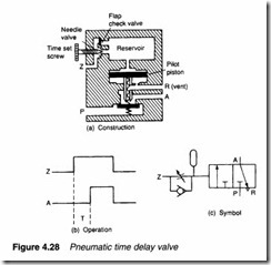
Pneumatic time delay valves (Figure 4.28) are used to delay operations where time-based sequences are required. Figure 4.28a shows construction of a typical valve. This is similar in construction to a 3/2 way pilot-operated valve, but the space above the main valve is comparatively large and pilot air is only allowed in via a flow reducing needle valve. There is thus a time delay between application of pilot pressure to port Z and the valve operation, as shown by the timing diagram in Figure 4.28b. The time delay is adjusted by the needle valve setting.
The built-in check valve causes the reservoir space above the valve to vent quickly when pressure at Z is removed to give no delay off.
The valve shown in Figure 4.28 is a normally-closed delay-on valve. Many other time delay valves (delay-off, delay on/off, normally-open) can be obtained. All use the basic principle of the air reservoir and needle valve.
The symbol of a normally-dosed time delay valve is shown in Figure 4.28c.
