Check valves
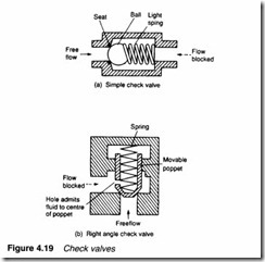
Check valves only allow flow in one direction and, as such, are similar in operation to electronic diodes. The simplest construction is the ball and seat arrangement of the valve in Figure 4.19a, commonly used in pneumatic systems. The right angle construction in Figure 4.19b is better suited to the higher pressures of a hydraulic
system. Free flow direction is normally marked with an arrow on the valve casing.
A check valve is represented by the graphic symbols in Figure The symbol in Figure 4.20a is rather complex and the simpler symbol in Figure 4.20b is more commonly used.
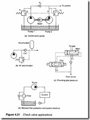
Figure 4.21 illustrates several common applications of check valves. Figure 4.21a shows a combination pump, used where an application requires large volume and low pressure, or low volume and high pressure. A typical case is a clamp required to engage quickly (high volume and low pressure) then grip (minimal volume but high pressure). Pump 1 is the high volume and low pressure pump, and pump 2 the high pressure pump. In high volume mode both pumps deliver to the system, pump 1 delivering through the check valve V3. When high pressure is required, line pressure at X rises operating unloading valve V 1 via pilot port Z taking pump 1 off load. Pump 2 delivers the required pressure set by relief valve V2, with the check valve preventing fluid leaking back to pump 1 and V 1.
Figure 4.21b shows a hydraulic circuit with a pressure storage device called an accumulator (described in a later chapter). Here a check valve allows the pump to unload via the pressure regulating valve, while still maintaining system pressure from the accumulator.
A spring-operated check valve requires a small pressure to open (called the cracking pressure) and acts to some extent like a low pressure relief valve. This characteristic can be used to advantage. In Figure 4.21c pilot pressure is derived before a check valve, and in Figure 4.21d a check valve is used to protect a blocked filter by diverting flow around the filter when pressure rises. A check valve is also included in the tank return to prevent fluid being sucked out of the tank when the pump is turned off.
Pilot-operated check valves
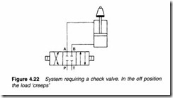
The cylinder in the system in Figure 4.22 should, theoretically, hold position when the control valve is in its centre, off, position. In practice, the cylinder will tend to creep because of leakage in the control valve.
Check valves have excellent sealage in the closed position, but a simple check valve cannot be used in the system in Figure 4.22 because flow is required in both directions. A pilot-operated check is similar to a basic check valve but can be held open permanently by application of an external pilot pressure signal.
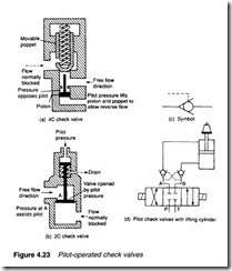
There are two basic forms of pilot-operated check valves, shown in Figure 4.23. They operate in a similar manner to basic check valves, but with pilot pressure directly opening the valves. In the 4C valve shown in Figure 4.23a, inlet pressure assists the pilot. The
symbol of a pilot-operated check valve is shown in Figure 4.23c.
The cylinder application of Figure 4.22 is redrawn with pilot operated check valves in Figure 4.23d. The pilot lines are connected to the pressure line feeding the other side of the cylinder. For any cylinder movement, one check valve is held open by flow (operating as a normal check valve) and the other is held open by pilot pressure. For no required movement, both check valves are closed and the cylinder is locked in position.
Restriction check valves
The speed of a hydraulic or pneumatic actuator can be controlled by adjusting the rate at which a fluid is admitted to, or allowed out from, a device. This topic is discussed in more detail in Chapter 5 but a speed control is often required to be direction-sensitive and this requires the inclusion of a check valve.
A restriction check valve (often called a throttle relief valve in pneumatics) allows full flow in one direction and a reduced flow in the other direction. Figure 4.24a shows a simple hydraulic valve and Figure 4.24b a pneumatic valve. In both, a needle valve sets restricted flow to the required valve. The symbol of a restriction check valve is shown in Figure 4.24c.
Figure 4.24d shows a typical application in which the cylinder extends at full speed until a limit switch makes, then extend further at low speed. Retraction is at full speed.
A restriction check valve V2 is fitted in one leg of the cylinder. With the cylinder retracted, limit-operated valve V3 is open allowing free flow of fluid from the cylinder as it extends. When the striker plate on the cylinder ram hits the limit, valve V3 closes and flow out of the cylinder is now restricted by the needle valve setting of valve V2. In the reverse direction, the check valve on valve V2 opens giving full speed of retraction.



Hi,
Thanks for the great details about valve, i have bookmarked your blog for the future updates.
We are leading manufacturers company engaged in Solenoid Valve, Get Valve, Pressure Relief Valve