LAMINAR FLOW IN TUBES
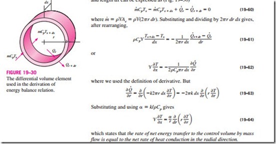
Reconsider steady laminar flow of a fluid in a circular tube of radius R. The fluid properties r, k, and Cp are constant, and the work done by viscous stresses is negligible. The fluid flows along the x-axis with velocity ‘V. The flow is fully developed so that ‘V is independent of x and thus ‘V = ‘V(r). Noting that energy is transferred by mass in the x-direction, and by conduction in the r-direction (heat conduction in the x-direction is assumed to be negligible), the steady-flow energy balance for a cylindrical shell element of thickness dr and length dx can be expressed as (Fig. 19–30)
which states that the rate of net energy transfer to the control volume by mass flow is equal to the net rate of heat conduction in the radial direction.
Constant Surface Heat Flux
For fully developed flow in a circular pipe subjected to constant surface heat flux, we have, from Eq. 19–50,
If heat conduction in the x-direction were considered in the derivation of Eq. 19–64, it would give an additional term aa2T/ax2, which would be equal to zero since aT/ax = constant and thus T = T(r). Therefore, the assumption that there is no axial heat conduction is satisfied exactly in this case.
Substituting Eq. 19–65 and the relation for velocity profile (Chap. 14) into Eq. 19–64 gives
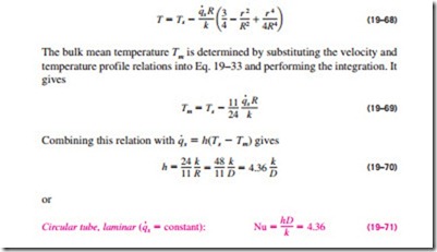
The desired solution to the problem is obtained by applying the boundary conditions aT/ax = 0 at r = 0 (because of symmetry) and T = Ts at r = R. We get
Therefore, for fully developed laminar flow in a circular tube subjected to constant surface heat flux, the Nusselt number is a constant. There is no dependence on the Reynolds or the Prandtl numbers.
Constant Surface Temperature
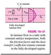
A similar analysis can be performed for fully developed laminar flow in a circular tube for the case of constant surface temperature Ts. The solution procedure in this case is more complex as it requires iterations, but the Nusselt number relation obtained is equally simple (Fig. 19–31):
The thermal conductivity k for use in the Nu relations above should be evaluated at the bulk mean fluid temperature, which is the arithmetic average of the mean fluid temperatures at the inlet and the exit of the tube. For laminar flow, the effect of surface roughness on the friction factor and the heat transfer coefficient is negligible.
Laminar Flow in Noncircular Tubes
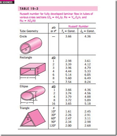
The Nusselt number relations are given in Table 19–3 for fully developed laminar flow in tubes of various cross sections. The Reynolds and Nusselt numbers for flow in these tubes are based on the hydraulic diameter Dh = 4Ac /p, where Ac is the cross-sectional area of the tube and p is its perimeter. Once the Nusselt number is available, the convection heat transfer coefficient is determined from h = kNu/Dh.
Developing Laminar Flow in the Entrance Region
For a circular tube of length L subjected to constant surface temperature, the average Nusselt number for the thermal entrance region can be determined from (Edwards et al., 1979)
Note that the average Nusselt number is larger at the entrance region, as expected, and it approaches asymptotically to the fully developed value of 3.66 as L ® x. This relation assumes that the flow is hydrodynamically developed when the fluid enters the heating section, but it can also be used approximately for flow developing hydrodynamically.
When the difference between the surface and the fluid temperatures is large, it may be necessary to account for the variation of viscosity with temperature.
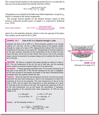
The average Nusselt number for developing laminar flow in a circular tube in that case can be determined from [Sieder and Tate (1936)]
