■ NATURAL CONVECTION FROM FINNED SURFACES AND PCBs
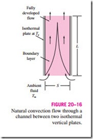
Natural convection flow through a channel formed by two parallel plates as shown in Fig. 20–16 is commonly encountered in practice. When the plates are hot (Ts > Too), the ambient fluid at Too enters the channel from the lower end, rises as it is heated under the effect of buoyancy, and the heated fluid leaves the channel from the upper end. The plates could be the fins of a finned heat sink, or the PCBs (printed circuit boards) of an electronic device. The plates can be approximated as being isothermal (Ts = constant) in the first case, and isoflux ( · = constant) in the second case.
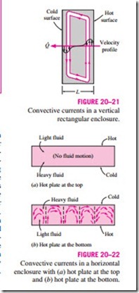
Boundary layers start to develop at the lower ends of opposing surfaces, and eventually merge at the midplane if the plates are vertical and sufficiently long. In this case, we will have fully developed channel flow after the merger of the boundary layers, and the natural convection flow is analyzed as channel flow. But when the plates are short or the spacing is large, the boundary layers of opposing surfaces never reach each other, and the natural convection flow on a surface is not affected by the presence of the opposing surface. In that case, the problem should be analyzed as natural convection from two in- dependent plates in a quiescent medium, using the relations given for surfaces, rather than natural convection flow through a channel.
Natural Convection Cooling of Finned Surfaces (Ts = constant)
Finned surfaces of various shapes, called heat sinks, are frequently used in the cooling of electronic devices. Energy dissipated by these devices is transferred to the heat sinks by conduction and from the heat sinks to the ambient air by natural or forced convection, depending on the power dissipation requirements. Natural convection is the preferred mode of heat transfer since it involves no moving parts, like the electronic components themselves. However, in the natural convection mode, the components are more likely to run at a higher temperature and thus undermine reliability. A properly selected heat sink may considerably lower the operation temperature of the components and thus reduce the risk of failure.
Natural convection from vertical finned surfaces of rectangular shape has been the subject of numerous studies, mostly experimental. Bar-Cohen and Rohsenow (1984) have compiled the available data under various boundary conditions, and developed correlations for the Nusselt number and optimum spacing. The characteristic length for vertical parallel plates used as fins is usually taken to be the spacing between adjacent fins S, although the fin height L could also be used. The Rayleigh number is expressed as
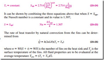
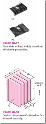
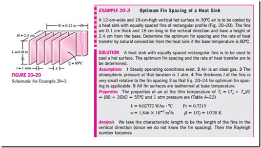
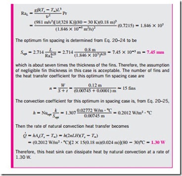
A question that often arises in the selection of a heat sink is whether to select one with closely packed fins or widely spaced fins for a given base area (Fig. 20–17). A heat sink with closely packed fins will have greater surface area for heat transfer but a smaller heat transfer coefficient because of the extra resistance the additional fins introduce to fluid flow through the interfin passages. A heat sink with widely spaced fins, on the other hand, will have a higher heat transfer coefficient but a smaller surface area. Therefore, there must be an optimum spacing that maximizes the natural convection heat transfer from the heat sink for a given base area WL, where W and L are the width and height of the base of the heat sink, respectively, as shown in Fig. 20–18. When the fins are essentially isothermal and the fin thickness t is small relative to the fin spacing S, the optimum fin spacing for a vertical heat sink is determined by Bar-Cohen and Rohsenow to be
Natural Convection Cooling of Vertical PCBs
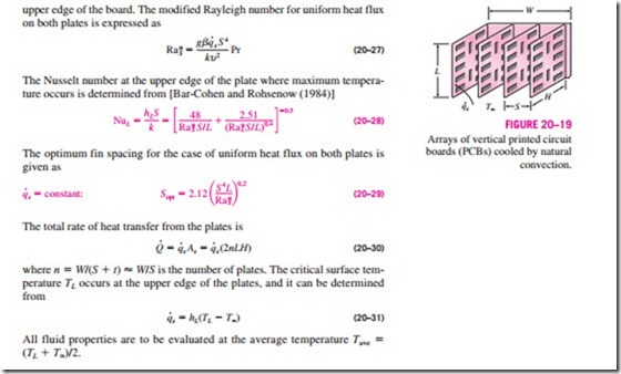
Arrays of printed circuit boards used in electronic systems can often be modeled as parallel plates subjected to uniform heat flux · (Fig. 20–19). The plate temperature in this case increases with height, reaching a maximum at the upper edge of the board. The modified Rayleigh number for uniform heat flux on both plates is expressed as
Mass Flow Rate through the Space between Plates
As we mentioned earlier, the magnitude of the natural convection heat transfer is directly related to the mass flow rate of the fluid, which is established by the dynamic balance of two opposing effects: buoyancy and friction.
The fins of a heat sink introduce both effects: inducing extra buoyancy as a result of the elevated temperature of the fin surfaces and slowing down the fluid by acting as an added obstacle on the flow path. As a result, increasing the number of fins on a heat sink can either enhance or reduce natural convection, depending on which effect is dominant. The buoyancy-driven fluid flow rate is established at the point where these two effects balance each other. The friction force increases as more and more solid surfaces are introduced, seriously disrupting fluid flow and heat transfer. Under some conditions, the increase in friction may more than offset the increase in buoyancy. This in turn will tend to reduce the flow rate and thus the heat transfer. For that reason, heat sinks with closely spaced fins are not suitable for natural convection cooling.
When the heat sink involves closely spaced fins, the narrow channels formed tend to block or “suffocate” the fluid, especially when the heat sink is long. As a result, the blocking action produced overwhelms the extra buoy- ancy and downgrades the heat transfer characteristics of the heat sink. Then, at a fixed power setting, the heat sink runs at a higher temperature relative to the no-shroud case. When the heat sink involves widely spaced fins, the shroud does not introduce a significant increase in resistance to flow, and the buoyancy effects dominate. As a result, heat transfer by natural convection may improve, and at a fixed power level the heat sink may run at a lower temperature.
When extended surfaces such as fins are used to enhance natural convection heat transfer between a solid and a fluid, the flow rate of the fluid in the vicinity of the solid adjusts itself to incorporate the changes in buoyancy and friction. It is obvious that this enhancement technique will work to advantage only when the increase in buoyancy is greater than the additional friction introduced. One does not need to be concerned with pressure drop or pumping power when studying natural convection since no pumps or blowers are used in this case. Therefore, an enhancement technique in natural convection is evaluated on heat transfer performance alone.
The failure rate of an electronic component increases almost exponentially with operating temperature. The cooler the electronic device operates, the more reliable it is. A rule of thumb is that the semiconductor failure rate is halved for each 10°C reduction in junction operating temperature. The de- sire to lower the operating temperature without having to resort to forced convection has motivated researchers to investigate enhancement techniques for natural convection. Sparrow and Prakash have demonstrated that, under certain conditions, the use of discrete plates in lieu of continuous plates of the same surface area increases heat transfer considerably. In other experimental work, using transistors as the heat source, Çengel and Zing have demonstrated that temperature recorded on the transistor case dropped by as much as 30°C when a shroud was used, as opposed to the corresponding no- shroud case.
Incoming search terms:
- amazon
- closely packed fins
- why are heat sinks with closely packed fins not suitable for natural
- why heat sinks with closely packed fins not suitable
