■ THE IDEAL VAPOR-COMPRESSION REFRIGERATION CYCLE
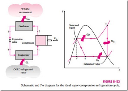
Many of the impracticalities associated with the reversed Carnot cycle can be eliminated by vaporizing the refrigerant completely before it is compressed and by replacing the turbine with a throttling device, such as an expansion valve or capillary tube. The cycle that results is called the ideal vapor- compression refrigeration cycle, and it is shown schematically and on a T–s diagram in Fig. 8–53. The vapor-compression refrigeration cycle is the most widely used cycle for refrigerators, air-conditioning systems, and heat pumps. It consists of four processes:
1-2 Isentropic compression in a compressor
2-3 Constant-pressure heat rejection in a condenser
3-4 Throttling in an expansion device
4-1 Constant-pressure heat absorption in an evaporator
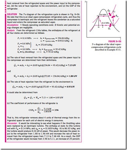
In an ideal vapor-compression refrigeration cycle, the refrigerant enters the compressor at state 1 as saturated vapor and is compressed isentropically to the condenser pressure. The temperature of the refrigerant increases during this isentropic compression process to well above the temperature of the surrounding medium. The refrigerant then enters the condenser as superheated vapor at state 2 and leaves as saturated liquid at state 3 as a result of heat rejection to the surroundings. The temperature of the refrigerant at this state is still above the temperature of the surroundings.
The saturated liquid refrigerant at state 3 is throttled to the evaporator pressure by passing it through an expansion valve or capillary tube. The temperature
of the refrigerant drops below the temperature of the refrigerated space during this process. The refrigerant enters the evaporator at state 4 as a low-quality saturated mixture, and it completely evaporates by absorbing heat from the refrigerated space. The refrigerant leaves the evaporator as saturated vapor and reenters the compressor, completing the cycle.
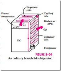
In a household refrigerator, the tubes in the freezer compartment where heat is absorbed by the refrigerant serves as the evaporator. The coils behind the re- frigerator, where heat is dissipated to the kitchen air, serve as the condenser (Fig. 8–54).
Remember that the area under the process curve on a T–s diagram represents the heat transfer for internally reversible processes. The area under the process Freezer curve 4-1 represents the heat absorbed by the refrigerant in the evaporator, and the area under the process curve 2-3 represents the heat rejected in the condenser. A rule of thumb is that the COP improves by 2 to 4 percent for each C the evaporating temperature is raised or the condensing temperature is lowered.
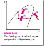
Another diagram frequently used in the analysis of vapor-compression refrigeration cycles is the P–h diagram, as shown in Fig. 8–55. On this diagram, three of the four processes appear as straight lines, and the heat transfer in the condenser and the evaporator is proportional to the lengths of the corresponding process curves.
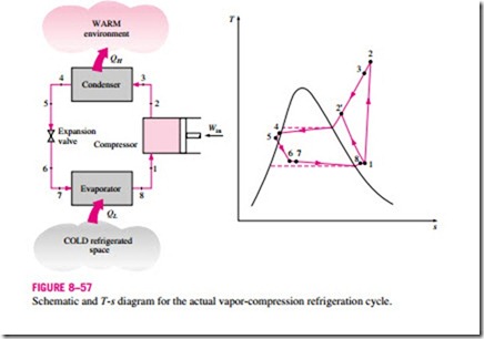
Notice that unlike the ideal cycles discussed before, the ideal vapor-compression refrigeration cycle is not an internally reversible cycle since it involves an irreversible (throttling) process. This process is maintained in the cycle to make it a more realistic model for the actual vapor-compression
refrigeration cycle. If the throttling device were replaced by an isentropic turbine, the refrigerant would enter the evaporator at state 4′ instead of state 4. As a result, the refrigeration capacity would increase (by the area under process curve 4′-4 in Fig. 8–53) and the net work input would decrease (by the amount of work output of the turbine). Replacing the expansion valve by a turbine is not practical, however, since the added benefits cannot justify the added cost and complexity.
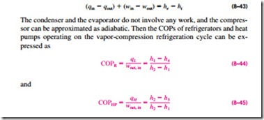
All four components associated with the vapor-compression refrigeration cycle are steady-flow devices, and thus all four processes that make up the cycle can be analyzed as steady-flow processes. The kinetic and potential energy changes of the refrigerant are usually small relative to the work and heat transfer terms, and therefore they can be neglected. Then the steady-flow energy equation on a unit-mass basis reduces to
where h1 = hg @ P and h3 = hf @ P for the ideal case.
Vapor-compression refrigeration dates back to 1834 when the Englishman Jacob Perkins received a patent for a closed-cycle ice machine using ether or other volatile fluids as refrigerants. A working model of this machine was built, but it was never produced commercially. In 1850, Alexander Twining began to design and build vapor-compression ice machines using ethyl ether, which is the commercially used refrigerant in vapor-compression systems. Initially, vapor-compression refrigeration systems were large and were mainly used for ice making, brewing, and cold storage. They lacked automatic controls and were steam-engine driven. In the 1890s, electric-motor driven smaller machines equipped with automatic controls started to replace the older units, and refrigeration systems began to appear in butcher shops and house- holds. By 1930, the continued improvements made it possible to have vapor- compression refrigeration systems that were relatively efficient, reliable, small, and inexpensive.
Incoming search terms:
- ideal refrigeration cycle
- vapor compression refrigeration cycle
- ideal vapour compression cycle
- refrigeration cycle
- What is ideal vapour refrigerator cycle
- vapour compression cycle
- vapor cycle
- vapor compression refrigeration cycle picture
- vapor compression refri
- the ideal vapor compression refrigeration cycle
- power and refrigerator cycle
- ph diagram of vapour compression refrigeration cycle with thermodynamic process
- ideal vapor compression refrigeration cycle
- write down assumption ideal vapour compression cycle
