ENERGY BALANCE FOR STEADY-FLOW SYSTEMS
A large number of engineering devices such as turbines, compressors, and nozzles operate for long periods of time under the same conditions once the transient start-up period is completed and steady operation is established, and they are classified as steady-flow devices. Processes involving such devices can be represented reasonably well by a somewhat idealized process, called the steady-flow process, which was defined previously as a process during which a fluid flows through a control volume steadily. That is, the fluid properties can change from point to point within the control volume, but at any point, they remain constant during the entire process. (Remember, steady means no change with time.)
During a steady-flow process, no intensive or extensive properties within the control volume change with time. Thus, the volume V, the mass m, and the total energy content E of the control volume remain constant (Fig. 5–22). As a result, the boundary work is zero for steady-flow systems (since VCV = constant), and the total mass or energy entering the control volume must be equal to the total mass or energy leaving it (since mCV = constant and ECV = constant). These observations greatly simplify the analysis.
The fluid properties at an inlet or exit remain constant during a steady-flow process. The properties may, however, be different at different inlets and ex- its. They may even vary over the cross section of an inlet or an exit. However, all properties, including the velocity and elevation, must remain constant with time at a fixed point at an inlet or exit. It follows that the mass flow rate of the fluid at an opening must remain constant during a steady-flow process (Fig. 5–23). As an added simplification, the fluid properties at an opening are usually considered to be uniform (at some average value) over the cross sec- tion. Thus, the fluid properties at an inlet or exit may be specified by the average single values. Also, the heat and work interactions between a steady delivered by a system and the rate of heat transfer to or from a system remain constant during a steady-flow process.
The mass balance for a general steady-flow system can be expressed in the rate form as
where the subscript i stands for inlet and e for exit, and the summation signs are used to emphasize that all the inlets and exits are to be considered.
Most engineering devices such as nozzles, diffusers, turbines, compressors, and pumps involve a single stream (one inlet and one exit only). For these cases, we denote the inlet state by the subscript 1 and the exit state by the sub- script 2, and drop the summation signs. Then the mass balance for a single- stream steady-flow system becomes
where r is density, ‘V is the average flow velocity in the flow direction, and A is the cross-sectional area normal to the flow direction.
Energy Balance for Steady-Flow Systems
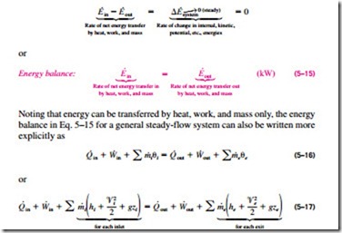
During a steady-flow process, the total energy content of a control volume re- mains constant (ECV = constant), and thus the change in the total energy of the control volume is zero (�ECV = 0). Therefore, the amount of energy entering a control volume in all forms (by heat, work, and mass) must be equal to the amount of energy leaving it. Then the rate form of the general energy balance reduces for a steady-flow process to
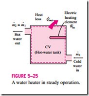
since the energy of a flowing fluid per unit mass is e = h + ke + pe = h + ‘V2/2 + gz. The energy balance relation for steady-flow systems first appeared in 1859 in a German thermodynamics book written by Gustav Zeuner. Consider, for example, an ordinary electric hot-water heater under steady operation, as shown in Fig. 5–25. A cold-water stream with a mass flow rate m· is continuously flowing into the water heater, and a hot-water stream of the same mass flow rate is continuously flowing out of it. The water heater (the control volume) is losing heat to the surrounding air at a rate of · , and
the electric heating element is supplying electrical work (heating) to the water at a rate of · . On the basis of the conservation of energy principle, we can say that the water stream will experience an increase in its total energy as it flows through the water heater that is equal to the electric energy supplied to the water minus the heat losses.
The energy balance relation just given is intuitive in nature and is easy to use when the magnitudes and directions of heat and work transfers are known. When performing a general analytical study or solving a problem that involves an unknown heat or work interaction, however, we need to assume a direction for the heat or work interactions. In such cases, it is common practice to assume heat to be transferred into the system (heat input) at a rate of · , and work produced by the system (work output) at a rate of W, and then solve the problem. The first-law or energy balance relation in that case for a general steady-flow system becomes
That is, the rate of heat transfer to a system minus power produced by the sys- tem is equal to the net change in the energy of the flow streams. Obtaining a negative quantity for Q or W simply means that the assumed direction for that quantity is wrong and should be reversed.
For single-stream (one-inlet–one-exit) systems, the summations over the in- lets and the exits drop out, and the inlet and exit states in this case are denoted by subscripts 1 and 2, respectively, for simplicity. The mass flow rate through the entire control volume remains constant (m· 1 = m· 2) and is denoted by m· .
Then the energy balance for single-stream steady-flow systems becomes
where q = Q /m· and w = W/m· are the heat transfer and work done per unit mass of the working fluid, respectively.
If the fluid experiences a negligible change in its kinetic and potential energies as it flows through the control volume (that is, �ke � 0, �pe � 0), then the energy equation for a single-stream steady-flow system reduces further to
The various terms appearing in the above equations are as follows:
Q = rate of heat transfer between the control volume and its surroundings. When the control volume is losing heat (as in the
case of the water heater), · is negative. If the control volume is well insulated (i.e., adiabatic), then Q = 0.
W = power. For steady-flow devices, the control volume is constant; thus, there is no boundary work involved. The work required to push mass into and out of the control volume is also taken care of by using enthalpies for the energy of fluid streams instead of internal energies.
Then · represents the remaining forms of work done per unit time (Fig. 5–26). Many steady-flow devices, such as turbines, compressors, and pumps, transmit power through a shaft, and · simply becomes the shaft power for those devices. If the control surface is crossed by electric wires (as in the case of an electric water heater), · will represent the electrical work done per unit time. If neither is present, then · = 0.
�h = hexit hinlet. The enthalpy change of a fluid can easily be determined by reading the enthalpy values at the exit and inlet states from the tables. For ideal gases, it can be approximated by �h = Cp, av(T2 – T1). Note that (kg/s)(kJ/kg) kW.
�ke = (‘V2 – ‘V2)/2. The unit of kinetic energy is m2/s2, which is
To add these two quantities, the kinetic energy should be expressed in kJ/kg. This is easily accomplished by dividing it by 1000.
A velocity of 45 m/s corresponds to a kinetic energy of only 1 kJ/kg, which is a very small value compared with the enthalpy values encountered in practice. Thus, the kinetic energy term at low velocities can be neglected. When a fluid stream enters and leaves a steady-flow device at about the same velocity (‘V � ‘V ), the change in the kinetic
energy is close to zero regardless of the velocity. Caution should be exercised at high velocities, however, since small changes in velocities may cause significant changes in kinetic energy (Fig. 5–28).
�pe = g(z2 – z1). A similar argument can be given for the potential energy term. A potential energy change of 1 kJ/kg corresponds to an elevation difference of 102 m. The elevation difference between the inlet and exit of most industrial devices such as turbines and compressors is well below this value, and the potential energy term is always neglected for these devices. The only time the potential energy term is significant is when a process involves pumping a fluid to high elevations and we are interested in the required pumping power.


