CONVERTING SCFM INTO COMPRESSOR HORSEPOWER
Compression of air is an inefficient process because part of the energy is lost as heat of compression and can never be recovered. Overcompressing the air and then reducing
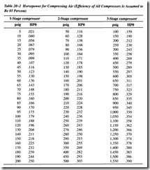
it to a lower pressure through a regulator increases the system losses. The amount of this loss is nearly impossible to calculate, but on the average system may amount to 5 or 10 percent. Also, there is a small loss due to flow resistance through the regulator. After finding the scfm to operate the cylinder, refer to Table 20-2. Convert into horse power according to the kind of compressor used. Add 5 to 10 percent for the miscellaneous losses described above. This should be very close to the actual horsepower capacity needed.
One important use for this table is to estimate the compressor horsepower capacity needed to operate an air cylinder. The scfm required by the cylinder under stated oper ating conditions must first be calculated by the method discussed earlier. Then the appropriate column in the table can be used to convert scfm into horsepower. For example, if cylinder consumption has been calculated to be 24 scfm, and if the com pressor is a two-stage model, the horsepower needed at 90 psig will be:
AIR CYLINDER FORCE
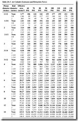
In Table 20-3, cylinder forces are shown in pounds for both extension and retraction. Lines in bold type show extension forces, using the full piston area. Lines in italic type show retraction forces with various size piston rods. Remember that force values are theoretical, derived by calculation.
Pressures along the top of the chart do not represent air supply pressure; they are dif ferential pressures across the two cylinder ports. In practice, the air supply line must supply another 5 percent of pressure to make up for cylinder loss, and must supply an estimated 25 to 50 percent additional pressure to make up for flow losses in lines and valving so the cylinder will have sufficient travel speed.
For good design and highest circuit efficiency, open the cylinder speed control valves as wide as practical and reduce the pressure regulator setting to as low a pressure as will give satisfactory cylinder force and speed. For pressures not shown, use the effective areas in the third column as power factors. Multiply effective area times differen- tial pressure to obtain theoretical cylinder force.


