AIR RECEIVERS
A compressor plant normally includes one or more pressure vessels known as air receivers which provide the following functions:
• Equalisation of pressure variations in the supply lines.
• Storage of compressed air to meet heavy demands in excess of the compressor capacity.
• A source of additional cooling and a collection point for residual condensate and oil droplets.
• Prevention of rapid loading and unloading of the compressor in short cycle duties.
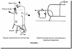
The usual form of receiver is illustrated in Figure I. The detailed design of such a vessel is covered by a number of standards (see below).
Storage capacity
The useful capacity of a receiver is the volume of free air which can be drawn from it at its design pressure; this is, of course, different from its actual internal volume. The size of the air receiver depends on the duty it is required to fulfil. The simplest duty required is one in which the demand is constant and reasonably close to that ofthe compressor output. A rule-of-thumb guide for receiver size in this situation, where the pressure is less than 9 bar, is six times the compressor flow rate per second or 0.1 times the flow rate per minute. This rule applies only where the control system involves automatic valve unloading, and where the difference between the loading and reloading of the system is no less than about bar. If the pressure is higher than 9 bar, a rather smaller receiver will be acceptable.
If the demand is variable, the calculation of receiver size depends on the acceptable pressure drop and the number of cycles of loading and unloading that are permissible per unit time. For a very variable demand, the receiver volume should be about three times that calculated for uniform demand.
In a situation where the air demand is intermittent, requiring a fairly large volume flow for a short period of time with no demand at all for the remainder of the time, it is worthwhile performing a calculation to determine the most economical combination of compressor and receiver. Take as an example an application in which 60m3/min at 7 bar is required to be delivered for I0 minutes every hour. Clearly one solution would be to have a compressor capable of 60 m 3/min working for only those ten minutes. Since the mean flow is only 60 + 6 = lO m 3/min, another solution would be to have a smaller compressor working continuously and storing its excess in a large receiver. The smaller compressor would have a higher pressure rating and the excess flow for 50 minutes would be stored in the receiver at that pressure.
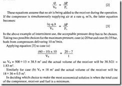
The fundamental equation relating pressure drop to receiver volume is:
pis the pressure drop (bar) experienced in the receiver during the operation Po is atmospheric pressure in bar
If the operation is identified by a flow rate q in m3/s over a time t, this equation can be rewritten as:
In deciding which choice to make the most economical solution is when the total cost of the compressor, receiver and fuel is a minimum.
Receiver volume calculations in automatic start/stop control
If the control system involves stopping and starting of the motor, then a receiver much larger than that for automatic unloading is required so as to avoid too rapid a cycling of the controls. The primary requirement is that the receiver must be sized so that no more than about ten starts per hour, evenly spread, take place; this is so that damage to the starter system and the motor windings is avoided. The spread of pressure should be as large as can be tolerated to further reduce the number of cycles. The compressor manufacturer will normally calculate the correct receiver size based on the control system used.
Equation [3] can be rewritten as
and, in this instance, tis the time between successive starts of the compressor jf is the actual air demand as a fraction of the amount delivered by the compressor. It turns out that the worst condition for frequency of stops and starts is where jl = 0.5, ie when the demand is half the supply. If the demand is greater or less than a half, the number of stops is less frequent so this condition is usually taken as the design point. Replacing jl by 0.5, equation [4] becomes:
This comparison between the two values for the volume indicates the importance of assessing the correct receiver size to meet the requirements of the system.
Air receiver legislation in the U.K.
There is a large legislative framework governing the whole area of receiver design and certification which needs much study before it can be applied with confidence.
The Health and Safety at Work Act 1974 places a general duty on a number of persons involved with matters of safety; the duties are shared by designers, manufacturers, suppliers, importers employers, employees etc. Regulations in specific branches of industry have been made under the Act. The primary document on press uri sed systems (of which air receivers are usually the most critical element) is The Pressure Systems and Transportable Gas Containers Regulations 1989 (SI 1989 No 2169), all of which are now in effect. These Regulations implement EC Directive 76/767/EEC. The Health and Safety Executive have prepared a Code of Practice- Safety of Pressure Systems -which gives practical guidance on these Regulations. The British Compressed Air Society have gone further and have produced a comprehensive set of Guidance and Interpretation Notes which should be studied alongside the two official documents.
It should be noted that these Regulations repeal much of the Factories Act 1961 insofar as it related to pressure vessels, however vessels already in use and bearing markings made in accordance with the Act will not have to be changed unless they are modified subsequently.
The Regulations do not give detailed design methods (reference must be made to the appropriate Standards for these) but are concerned with ensuring that pressure systems falling within their scope are properly made, inspected, maintained and marked so as to safeguard those persons affected. The intention is to prevent the risk of injury from the release of the stored energy in a compressed air system. They are in fact wider in scope than compressed air and encompass steam, gases and mixed liquids and gases. The complete system includes the pressure vessels, pipework and any protective devices, where the pressure is in excess of 0.5 bar. If the complete system does not incorporate an air receiver, it may not be covered by the Regulations but it would be unwise to assume that to be the case without expert advice.
In the Regulations a system can be classified as Minor, Intermediate or Major, depending on theproductofthegaugepressureofthesystemin bar and the internal volume in litres (ie the product PS.V).
A minor system has a maximum operating pressure below 20 bar (gauge), the largest pressure vessel in the system has a PS.V Jess than 2 x I 05 bar litres and the operating temperature between -20°C and 250°C.
An intermediate system is one which either
(a) has a system pressure of 20 bar or above where PS.V is less than I x I06 bar Iitres or
(b) has a system pressure less than 20 bar and a PS.V greater than 2 x 10⁵ but less than 106 bar litres.
A major system is one in which PS.V is greater than I x 106 bar Iitres.
If PS.V is less than 250, certain of the Regulations do not apply (particularly in respect of marking), although such a vessel may come within the scope of the Simple Pressure Vessels Regulations, see below.
Most compressed air systems will fall into the Minor category. The Regulations place a different burden on the organisation responsible for carrying out the inspection and operation of the system according to the category in which it falls and defines the levels, qualification and experience of the “competent person” who draws up an examination scheme.
The Simple Pressure Vessels (Safety) Regulations I99I (SI 2749) apply to smaller pressure vessels. These Regulations are the national implementation of EC Directive 87/404/EEC (amended by 90/488/EEC). A simple pressure vessel is defined as one which is welded and made of non-alloy steel or non-alloy aluminium or non-age hardening aluminium alloy; the simple construction implies that it is to be cylindrical with convex ends or hemispherical; it must have a working pressure not greater than 30 bar and the product of the working pressure and the volume is not to exceed lO 000 bar Jitres. A pressure vessel coming under these regulations can be classified as AI, A2, A3 orB, depending on the product of the gauge working pressure and the internal volume (PS.V):
Different Regulations apply to the different categories, the main differences being the type of certification procedure which must be applied.
Meeting the requirements ofSI 2749 may be less onerous than SI 2169, so it is important to determine into which category and sub-category a particular pressure vessel falls and establish the inspection and certification procedure accordingly.
Most compressed air systems containing a receiver will fall within the scope of the Simple Pressure Vessels Directive.
Countries other than the U.K.
For members of the European Community other than the U.K., the same EC Directives apply, which makes for simplicity in design and certification and ensures that a pressure vessel acceptable in one European country will be equally acceptable to the others. For other countries general reference should be made to Boilers and ‘Pressure Vessels- An International Survey of Design and Approval Requirements’ published by BSI. This is a comprehensive reference to the national regulations, design codes and approval organi sations of a large number of countries. Fortunately European and American Codes are widely acceptable. In a subject which is constantly changing, the latest edition of this publication should be studied.
Design of pressure vessels
There are three British Standards to which reference should be made for information about design, manufacture and inspection- BS 5169: 1992, BS 5169:1975, BS 5500: 1994 and BS EN 286.
BS 5169 gives information specific to fusion welded steel air receivers (excluding vessels covered by SI 2749).
• BS EN 286 replaces BS 5169:1975 and is for vessels covered by SI 2749. It is for simple unfired pressure vessels designed for air or nitrogen.
These two are mutually exclusive.
• BS 5500 is for unfired fusion welded presure vessels.
BS 5500 is a comprehensive work with a wealth of material on all aspects of welded pressure vessels and should be studied by anyone embarking on the design. This chapter can only give an outline of the straightforward principles of design of receivers. For more complex matters such as the design of flanges, reinforcement of access openings, numbers and location of bolts and welding sizes, the original standards must be referred to. Computer programmes are available which remove some of the burden of calculations.
Materials for manufacture
A limited range of materials is permissible to meet the requirements of the standards. Reference should be made therein. Broadly certain steel grades contained in BS I 0207 and BS 10208 are acceptable for plates, strip and bar; material for tubes and forgings are specified in ISO 2604. For aluminium and aluminium alloys refer to the standard.
Design in accordance with BS 5169
BS 5169 specifies three classes of air receivers:
Class I-No limitation is placed on the design but all welded seams require non-destructive testing.
Class II- The design pressure shall not exceed 35 bar and the product of design pressure and internal diameter shall not exceed 37 000 bar mm.
Class III- The design pressure shall not exceed 17.5 and the product of design pressure and internal diameter shall not exceed 8800 bar mm.
Wall thicknesses
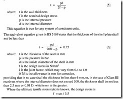
Simple theory for determining the thickness of a cylinder subject to internal pressure produces the relationship:
providing that in no case shall the thickness be less than 4 mm, or, in the case of Class III receivers where the internal diameter does not exceed 300, the thickness shall be not less than 2.5 mm or 0.01 D, whichever is the greater.
Where the ultimate tensile stress (uts) is known, the design stress is
f = uts I 3.5
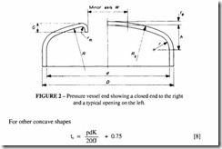
Design of ends
Ends shall be hemispherical or semi-ellipsoidal and may have manholes or hand holes. In the case of Class II and Class III receivers, and Class I receivers where the internal diameter does not exceed 600 mm, flat ends are permitted. If semi-ellipsoidal ends are chosen, the ratio of the major axis to that of the minor axis shall not be greater than 2.25: I.
For hemispherical ends the thickness of the end plate shall not be less than
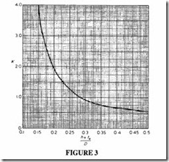
In both cases J = I for endplates made of one piece, and for plates made of more than one piece J is the appropriate factor obtained from the tables in the Standard. K depends on the ratio (h + t )ID, where h is the height of the height of the dished end and D is the outside diameter. K is read from Figure 3. In no case shall the thickness be less than that of the cy Iinder.
Openings in shells and plates
Openings have to be provided in receivers for the purpose of inspection, see Table 2. All openings have to be ring reinforced to strengthen the vessel in the region of the material removed. A good design guide is to make the ring from as much material as was removed. Refer to the standard for details.
Design in accordance with BS EN 2186
The alternative procedure of this document is confusing to the designer used to the earlier standards because the notation and the way in which the equations are expressed are different. Air receivers made in accordance with this standard are of simple construction, primarily welded and seriaiiy made. Ifpossible this standard is preferred provided that the conditions it covers are met.
The normal design stress is the lower value of 0.6 ReT or 0.3 Rm ,where ReT is the guaranteed minimum tensile yield strength and Rm is the guaranteed minimum tensile strength.
The normal thickness (e) takes account of corrosion and tolerance in the specification of the material thickness.
where ec is the calculated thickness s is the corrosion allowance
c is the absolute value of the negative tolerance on the material thickness. There may also be an extra allowance to cater for thinning in production.
The above treatment is only an outline of the general approach to the design of air receivers. Any serious designer should study the full standards; they contain a great deal of useful material. A competent person, as defined in the Regulations must demonstrate a fuii understanding of the appropriate standards.
