Dense phase plug flow
Polyethylene pellets have been selected as being representative of materials conveyed in dense phase in plug flow and the conveying characteristics are presented in Figure 13.7. These were presented earlier in Figure 12.11c. In Figure 13.7 they are shown with the
inclusion of lines of constant conveying line inlet air velocity and are taken to a convey- ing line pressure drop of 1.8 bar for direct comparison with the other materials being considered here.
With this material there is a complete reversal in slope of the constant pressure drop curves at low values of air flow rate. In the high velocity dilute phase conveying region the performance and behaviour of the material is no different from that of any other material conveyed in dilute phase flow. The minimum conveying air velocity with respect to dilute phase conveying with this material is about 15 m/s. From Figure 13.7 it will be seen that the change in slope of the constant pressure drop curves occurs approximately at a velocity of about 15 m/s.
Due to the positive slope of the curves in the low velocity dense phase region of the conveying characteristics the area available for dense phase conveying is rather limited and material flow rates are significantly reduced. Figure 13.7 would also indicate that at velocities below about 15 m/s the constant pressure drop curves appear to merge. This means that the flow could be very unstable in this region. In order to deter- mine how much of this is due to the small bore of the pipeline, tests were carried out with another material in a larger bore pipeline.
Tests with nylon pellets
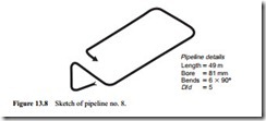
Tests were undertaken with nylon pellets in a similar pipeline to that used above for the polyethylene pellets except that it was 81 mm bore and so required about twice the amount of air for conveying [2]. A sketch of the pipeline is presented in Figure 13.8 for reference. A high pressure bottom discharge blow tank was used for the conveying trials with this material. The nylon pellets, like the polyethylene pellets, had a mean particle size of about 4 mm and were essentially mono-sized.
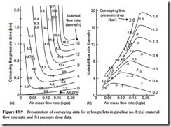
Since the conveying characteristics for this type of material are so very different from those of materials conveyed in sliding bed flow, actual test data is presented to show the range of conveying conditions covered. The data is presented on two plots, as with the cement in Figure 11.6. One is a plot of the material flow rate test results and the other is of the conveying line pressure drop data.
It will be seen from these two figures that the lines drawn fit the data very well and that there was very little scatter in the results. Although the resulting material flow rate
curves shown in Figure 13.9a are remarkably steep, which would tend to indicate that material flow rate control would be a problem, it will be seen from the data points that this was not the case. In Figure 13.9b the lines of constant pressure drop are very closely spaced and this is why they were seen to merge with the smaller bore pipeline. Data in Figure 13.9b are presented without hindrance of the test results in Figure 13.10a and lines of constant solids loading ratio are added.
It will be seen that the maximum value of solids loading ratio is very similar to that achieved with the polyethylene pellets. In Figure 13.10b lines of constant conveying line inlet air velocity have been superimposed and the horizontal air mass flow rate axis has been replaced with one of conveying line exit air velocity. Once again the pressure minimum points on the conveying characteristics correspond with a conveying line inlet air velocity of about 12 m/s which will be close to minimum conveying air velocity with the material conveyed in dilute phase suspension flow.

