COMPRESSOR CONTROLS
Compressor flow rate must be regulated to match the system demand. Usually the dis charge pressure is the controlled variable. The type of control depends upon the character istics of the compressor, the prime mover and the system. The control may be manual or automatic; it may be discontinuous (on-off) or continuous through speed variation of the motor and/or inlet throttling. Unloaded start of the compressor must be provided for if the torque of the prime mover is not sufficient to tum the compressor under load.
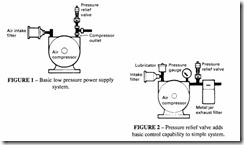
Smaller stationary compressors may be run continuously with only a blow-off (pressure relief valve) on the delivery side which opens when a specified maximum pressure is reached to allow compressed air to be blown off to atmosphere instead of being delivered to the system (Figure 1). This is a wasteful way of operation, since the prime mover is always working at its full power even though there may be no demanc from the system. If a receiver is included, a check valve may be used to prevent high pressure being blown back into the compressor (Figure 2). This is a!ways necessary with valveless compressors
Air intake filter
(eg vane or screw compressors) which might otherwise act as motors, driven backwards by the air in the system, but may not be necessary in piston or diaphragm types which have their own delivery valves. A check valve may still be used with the latter as a backflow protective device. A safety valve should also be incorporated in the system to protect against over-pressure. In this case, the safety valve would be set rather higher than the system operating pressure (about +I 0%).
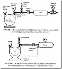
For continuous duty it may be desirable to maintain a higher pressure in the receiver than is required in the supply line. In this case, the receiver is followed by a pressure regulator (Figure 3).
An alternative method of pressure regulation for constant speed motor driven compres sors is by on-off cycling using an electrical pressure switch on the receiver to cut the motor supply at a predetermined ‘high’ pressure level, and back on again at a predetermined ‘low’ level (Figure 4). The receiver pressure is held between these pressures provided that the demand does not exceed the recharging capacity of the compressor.
Unloading
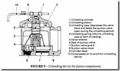
Larger systems are commonly operated with the compressor running continuously and the capacity regulated by unloading. One mechanical method used with reciprocating com pressors is shown in Figure 5.
Pressure from the receiver is transmitted to the underside of the piston of the device, which acts against a spring set at a predetermined pressure. When the pressure in the receiver exceeds this pressure, the spring compresses and allows air to flow to a piston on top of the suction valves which in turn depresses a claw which holds the suction valves off their seat, so that compression cannot take place in the cylinder. This is termed suction valve unloading.
When double-acting compressors are used, by having two air relays set at different
pressures, it is possible to unload each side of the piston in turn, giving full load, half load and zero load. This is three step unloading.
A variation of this method is to allow the inlet valves to open normally to fill the cylinders but to keep them open for a timed interval of the compression stroke, after which compression can begin. This can provide stepless regulation, but is normally used only with process compressors.
In clearance pocket control, one or more pockets containing added clearance volume are connected to the first stage cylinder, thereby lowering the volumetric efficiency and the amount of air delivered. These pockets may be manually or automatically controlled. The pockets usually have a fixed volume, but may have continuously variable pockets. A normal method on double acting compressors is to have a combination of clearance pocket and suction valve unloaders to give 100%-75%-50%-0% unloading.
Reverse flow regnlation
A method of stepless control suitable for reciprocating compressors is reverse flow regulation, by which the intake flow is caused to vary according to requirements, by
delaying the closing of the suction valves. This delayed closing is achieved by means of special unloaders. These are actuated by the variable pressure of a piston built into the valve cover (usually a diaphragm piston in a servo-cylinder). A number of unloader springs are tensioned by means of an unloader plate, which in turn keeps the valve plate of the regulated suction valve open against the reverse flow of gas during the compression stroke of the cylinder. Part of this gas flows back into the suction duct and reduces the output capacity by an equal amount. During the compression stroke, the velocity of the gas flowing back rises steadily with increasing piston speeds as do the flow forces acting on the unloader and valve plate in a closing action. These forces vary with piston position and eventually exceed the hold-open force which has been adjusted to a certain value. This causes the valve to close (after a delay) and the reverse flow is terminated. The remaining gas in the piston is compressed and discharged in the usual manner. This permits adjustment to any desired capacity between 100% and 40% of full load (see Figure 6) and in certain cases stepless reductions down to 15% or less may be achieved.
A further method of controlling the output is by throttling the intake, but this requires more power at part load conditions than the methods described above.
Screw compressors
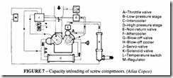
A different form of unloading is adopted in the case of screw compressors. The capacity is regulated by throttling the air intake and at the same time opening a blow-off valve. The pressure side is shut off with a non-return valve. Under load, the blow-off valve is closed and the throttle valve fully open. The unloading device is operated by a spring loaded automatic air relay of the same type as that used on reciprocating compressor controls. A complete system is shown in Figure 7.
Slide valve control for screw compressors
This type of control incorporates a third bore in the compressor casing, at the cusp of the rotor bores. In this bore is positioned a slide valve at the discharge side of the rotors.
As the compressor is off-loaded, the valve moves progressively opening up ports which connect the compressed air back into the inlet. This form of control is only suitable when the compressor is driven by a constant speed device such as an electric motor. Speed control is usually preferable, as well as being simpler.
Multi-pressure capability for screw compressors
It is sometimes convenient to supply a compressor with different pressure capabilities to meet the varying demands of the plant hire industry. It is clearly not possible in an installation with a fixed prime mover to supply a range of pressure capabilities while delivering the same output. However it is possible in a limited way to exchange delivery volume and pressure. This can be achieved by what amounts to a shortening of the LID ratio of the screw elements. A portion of the inlet length of the screws can be by-passed through one of a series of passages in the compressor casing, which vent some of the inlet air according to the desired pressure setting. The operating condition is set initially (which can be key locked to avoid improper use). Thus, in one particular compressor it is possible to have the following variations:
Unloading and speed control system in an engine driven screw compressor Compressor air output is controlled by a combination of an unloader valve which regulates the amount of air entering the compressor and a speed controller which varies the engine speed. An engine is not, of course, capable of running down to zero speed; typically a diesel engine can operate down to 50% of its maximum rated speed and still give a useful output, say from 2000 r/min down to I 000 r/min. It could still idle at less than 50% but the torque obtainable would not be sufficient to turn a screw. Usually the engine speed is reduced first
down to its minimum and intake throttling then takes over. Figure 8 shows a modern control system governing an engine driven compressor set at 7 bar pressure. This system includes a Start/Run valve for the warm up period, a pressure regulator valve set for the maximum compressor pressure and a blow down valve to release system pressure on shut down.
The unloader valve is situated in the inlet to the compressor. When the compressor is started the vacuum created in the unloader body causes the valve 15 to move against the spring 18. Air is then admitted to the compressor which builds up pressure in the pressure vessel II. This pressure is piped to the regulator 5 and the Start/Run valve 9. On start up, pressure passes through this valve and acts on the unloader piston 13 and speed control cylinder 12. When the pressure reaches 2.75 bar it moves the unloader valve to close off the air intake and moves the speed control cylinder to reduce engine speed to idling while the engine warms up. When the engine has reached operating temperature, the Start/Run valve is pressed which cuts off the air passing through it. The unloader valve piston then admits air to the compressor and the engine speeds up, to deliver air at a maximum of 7 bar. When that pressure is reached, the unloader valve and speed control cylinder move until air demand is exactly matched.
When the compressor is shut down correctly, the delivery cocks are first closed and the machine is then in the off-load condition. When the rotors stop, pressure in the vessel is prevented from getting to the inlet by the closed unloader valve. The remaining pressure then operates the blow-down valve to release all pressure in the system, which is then ready for the next start up. The blow-down valve ensures that the compressor cannot start against system pressure.
Control in multi-compressor installations
There are some advantages in industrial installations in having a number of separate compressors coupled together and feeding into the same supply line. Apart from the flexibility of being able to take an individual compressor out of service for maintenance and repair, there are possibilities inherent in this arrangement for designing a very efficient control for part-load operation. By adopting such a control system it has become possible to design rotary sets which approach the off-load efficiency of reciprocating units. In recent years the availability of cheap electronic control and sensing techniques has brought this type of approach into every day use.
There are several possibilities for this type of control, which in increasing order of complexity are:
Control using system pressure sensed by a pressure switch to switch on or off indiv idual compressors in a multi-set installation. Suitable for those installations with three or more compressors; this can be expensive because each compressor needs its own control card. The compressors could be switched in cascade or in ring sequence (to balance compressor use).
Simple stop/start suitable for small units (up to about 20 kW each) whereby a system pressure switch activates a timer which stops a compressor if the signal persists after say one minute.
• Auto-idling where the receiver pressure is vented in response to a signal from the system pressure switch after a predetermined time. After a further preset time the set is switched off completely.
Pulse-width modulation. The principle behind this development ensures that the individual compressor can operate at either full-load or idling. The system pressure is sensed as in the previous methods and the compression chamber pressure is switched between system pressure and atmospheric in a series of pulses with varying time widths. The receiver pressure is maintained at system pressure and isolated from the compression chamber by an unloader valve. A further modifica tion of this system is possible if the cycling time turns out to be too rapid. In this case the PWM is tempered by operating at intermediate steps of say 66% and 33% of full load.
Variable speed electric motor controls
Most electrically driven compressor sets use a constant speed motor, relying on intake throttling for capacity control. There is now coming on to the market an alternative form of capacity control using a variable speed electric motor drive (VSD). This works practically in much the same way as the engine speed control described above. The motive power comes from a variable speed, variable frequency induction motor. This has two major advantages: it is more efficient in part load operation, when compared with a compressor where the capacity control relies on modulation or on a basic load/no load regulation system; and it eliminates the need for a gear train. This form of control includes a frequency convertor in the compressor package and has other features which are possible using advanced electronic monitoring and control. The acceleration and deceleration levels can be controlled, which reduces the mechanical stress on the components of the
drive. The concept accurately measures system pressure and monitors the frequency convertor and speed so as to keep the delivery pressure constant within a narrow band.
While the system is more economical in running costs in an application where a substantial part of the time is at part load conditions, this must be offset against the extra capital costs. Figure 9 shows a completed packaged unit.
Compressor protection
Critical parameters which need to be maintained to provide basic protection for a compressor are coolant water flow or temperature, discharge air temperature and lubricat ing oil pressure or level (in the case of lubricated compressors). Typical minimum parameters, ie danger levels, might be:
• coolant water flow 2/3 of normal flow rate
• discharge air temperature 160°C
• lubricating oil pressure 2 bar
Temperature sensors and pressure sensors can provide cover for these. If temperature and pressure operated switches are used, they can provide automatic protection either as alarm devices or control devices, shutting down the system when a critical parameter level is reached.
Where compressors employ closed-circuit water cooling (either thermo-syphon or
