Hydraulic Power Drive Systems
The hydraulic power system, in its simplest form, consists of the following:
1. The prime mover, which is the outside source of power used to drive the hydraulic pump
2. A variable-displacement hydraulic pump
3. A hydraulic motor
4. A means of introducing a signal to the hydraulic pump to control its output
5. Mechanical shafting and gearing that transmits the output of the hydraulic motor to the equipment being operated
Hydraulic power drives differ in some respects, such as size and method of control. However, the fundamental operating principles are similar. The unit used in the fol lowing discussion of fundamental operating principles is representative of hydraulic power drives.
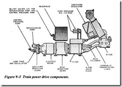
Figure 9-5 shows the basic components of a power drive. The electric motor is con structed with drive shafts at both ends. The forward shaft drives the A-end pump through reduction gears, and the after shaft drives the auxiliary pumps through the auxiliary reduction gears. The reduction gears are installed because the pumps are designed to operate at a speed much slower than that of the motor.
The replenishing pump is a spur gear-type pump. Its purpose is to replenish fluid to the active system of the power drive. It receives its supply of fluid from the reservoir and discharges it to the B-end valve plate. This discharge of fluid from the pump is held at a constant pressure by the action of a pressure relief valve.
The sump pump and oscillator has a twofold purpose. It pumps leakage, which col lects in the sump of the indicator regulator, to the expansion tank. Additionally, it transmits a pulsating effect to the fluid in the response pressure system. Oscillations in the hydraulic response system help eliminate static friction of valves, allowing hydraulic controls to respond faster.
The control pressure pump supplies high-pressure fluid for the hydraulic control sys tem, brake pistons, lock piston, and the hand-controlled clutch operating piston. The control pressure pump is fixed-displacement, axial-piston type. An adjustable relief valve is used to limit the operating pressure at the outlet of the pump.
Control
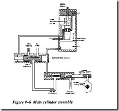
For the purpose of this text, control constitutes the relationship between the stroke control shaft and the tilting box. The stroke control shaft is one of the piston rods of a double-acting cylinder. This actuating cylinder and its direct means of control are referred to as the main cylinder assembly (Figure 9-6). It is the link between the hydraulic follow-up system and the power drive itself.
In hand control, the tilting box is mechanically positioned by gearing from the hand wheel through the A-end control unit. In local and automatic control, the stroke con trol shaft positions the tilting box. As shown in Figure 9-6, the extended end of the control shaft is connected to the tilting box. Movement of the shaft will pivot the tilt ing box one way or the other, which in tum controls the output of the A-end of the transmission. The other end of the shaft is attached to the main piston. A shorter shaft is attached to the opposite side of the piston. This shaft is also smaller in diameter. Thus, the working area of the left side of the piston is twice that of the right side, as it appears in Figure 9-6.
Intermediate high-pressure (IHP) fluid is transmitted to the left side of the piston, while high-pressure hydraulic (HPC) fluid is transmitted to the right side. The HPC is held constant at 1,000 psi. Since the area of the piston on which HPC acts is exactly one-half the area on which IHP acts, the main piston is maintained in a fixed position, when IHP is one-half (500 psi). Whenever IHP varies from its normal value of 500 psi, the main piston will move, thus moving the tilting box.
Operation
Assume that a right train order signal is received. This will cause the pilot valve to be pulled upward. The fluid in the upper chamber of the amplifier piston can now flow through the lower land chamber of the fine pilot to exhaust. This will cause the ampli fier piston to move upward, and the fluid in the right-hand chamber of the main control valve can flow into the lower chamber of the amplifier valve.
The main control valve will now move to the right, IHP will drop below 500 psi, and the stroke piston will move to the left. Movement of the stroke piston will cause tilt to be put on the tilt plate, and the A-end will cause the mount to train right.
Figure 9-7 is a simplified block diagram showing the main element of the hydraulic power drive system under automatic control for clockwise and counterclockwise rotation. There are two principal problems in positioning the unit. One is to get an accurate directional signal. This problem is solved by the director-computer combination. The other problem is to transmit the director signal promptly to the unit so that the position and movements of the unit will be synchronized with the signals from the director.
The power drive and its control-the indicator regulator-solve the problem of trans forming unit movement signals to the hydraulic system. The indicator regulator con trols the power drive and this in tum controls movement of the unit.
The indicator regulator receives an initial electrical signal from the director-com puter, compares it to the existing unit position, and sends an error signal to the hydraulic control mechanism in the regulator_ The hydraulic control mechanism con trols flow to the stroke control shaft, which positions the tilting box in the A-end of the transmission. Its tilt controls the volume and direction of fluid pumped to the B end and, therefore, the speed and direction of the drive shaft of the B-end_ Through mechanical linkage the B-end output shaft moves the unit in the direction determined by the input signal. At the same time, B-end response is transmitted to the indicator and continuously combines with incoming director signals to give the error between the two. This error is modified hydraulically, according to the system of mechanical linkages and valves in the regulator. When the unit is lagging behind the signal, its movement is accelerated; and when it begins to catch up, its movement is slowed down so that it will not overrun.
UNLOADING CIRCUITS
An unloading circuit is a system where a pump’s outlet is diverted to tank at low pres sure during part of the cycle. The pump may be unloaded because load conditions at times would exceed the available input power or simply to avoid wasting power and generating heat during idle periods.
Two-Pump Unloading System
It is often desirable to combine the delivery of two pumps for more speed while a cyl inder is advancing at low pressure. When the high speed is no longer required or the
pressure rises to the point where the combined volume of the two pumps would exceed the input horsepower, the larger of the two pumps is unloaded.
Low-Pressure Operation
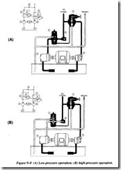
Figure 9-8, view A, shows the arrangement of components in such a system and the flow condition at low pressure. Oil from the larger volume pump passes through the unloading valve and over the check valve to combine with the low-volume pump out put. This condition continues so long as system pressure is lower than the setting of the unloading valve.
High-Pressure Operation
In view B, system pressure exceeds the setting of the unloading valve, which opens, permitting the large volume pump to discharge to the tank at little or no pressure. The check valve closes, preventing flow from the pressure line through the unloading valve.
In this condition, much less power is used than if both pumps had to be driven at high pressure. However, the final advance of the actuator is slower because of the smaller volume output to the system. When motion stops, the small-volume pump discharges over the relief valve at its unload setting.
Two Maximum Pressures plus Venting
The network shown in Figure 9-9 can be incorporated in a hydraulic system to allow selection of two maximum pressures as well as venting. The highest maximum pres sure will be set at the pilot stage of the main relief valve. The remote control relief valve can set a lesser pressure. The solenoid-operated four-way valve switches between the controls.
Venting
In view A of Figure 9-9, both solenoids of the directional control valve are de energized. The open-center spool is centered by the valve springs, and the vent port on the relief valve is opened to tank. The balanced piston opens and the pump’s flow is directed to the tank at the pressure equivalent to the light spring or about 20 psi.
Intermediate Maximum Pressure
In view B of Figure 9-9, the left-hand solenoid of the directional control valve is ener gized. The valve spool is shifted to connect the relief valve vent port to the remote controlled valve. This valve now operates as the pilot stage for the balanced piston. Pump flow is diverted to the tank when the remote valve setting is reached.
High Maximum Pressure
In view C of Figure 9-9, the opposite solenoid of the directional control valve is ener gized. The spool has shifted to connect the relief valve vent port to a deadheaded
against a plugged port in the directional control valve. The relief valve now functions at the setting of its integral pilot stage.


