Air venting
Unless the air leakage across the rotary valve is vented away, prior to the material entering the valve, material flow into the valve may be severely restricted. The magnitude of the problem depends very much upon the properties of the material being handled. For plastic pellets and granular materials, venting may not be necessary, but for fine cohesive materials and light fluffy materials the volumetric efficiency of the valve, in terms of pocket filling, may be very low. In this case material feed at a controlled rate might be difficult to achieve. A number of different ways of venting rotary valves are presented in Figure 3.10.
With pockets of material falling under gravity into a high pressure air stream, and a significant percentage of this air passing through the rotary valve, the turbulence generated beneath the rotary valve is considerable. It is not surprising, therefore, that this leakage air should carry a certain proportion of material with it, which is predominately dust and fines.
Since the vented air will contain some fine material, this is normally directed back to the supply hopper, or to a separate filter unit. Because there will be a carry-over of mater- ial this filter must be a regularly cleaned unit, otherwise it will rapidly block and cease to be effective. Indeed, the pipe connecting the vent to the filter should be designed and sized as if it were a miniature pneumatic conveying system, in order to prevent it from getting blocked.
A particular problem here is that the performance of such a peripheral item is rarely monitored, and so if the vent line does block it is rarely known or recognized as the source of subsequent operating problems.
Entrainment devices
In order to reduce the turbulence level, and hence energy loss, beneath a rotary valve, as a result of the pulsating nature of the material flow and opposing air flow, entrainment
devices are often used. A common device is a ‘drop-out’ box and this is illustrated in Figure 3.11.
Another configuration is the venturi entrainment section, and this is also shown in Figure 3.11. Here the cross section is reduced with a resultant increase in entrainment velocity and decrease in pressure in this region. A consequence of this decrease in static pressure is that there will be less leakage through the valve to interfere with material feeding, resulting in an improvement when handling the finer, free flowing types of material. As a consequence of the resulting high velocities this type of arrangement would not be recommended for either abrasive or friable materials.
Rotor types
Rotors are either of the ‘open-end’ type or ‘closed-end’ type. With ‘open-end’ types the blades are welded directly to the driving shaft, while with the ‘closed-end’ type discs or shrouds are welded to the shaft and blade ends to form enclosed pockets. These two types of rotor are illustrated in Figure 3.12.
Although open-end rotors are less expensive, they have several disadvantages. With the more abrasive materials wear of the rotor housing end plates is possible since the material is in constant contact with them. Also, they are not as rigid as the closed- end type as they only have one edge secured to the drive shaft. They cannot, of course, be used in the blow-through type of feeder shown in Figure 3.5b. The closed-end type of rotor provides a very much more rigid construction, and it is with this type of rotor that developments towards much higher pressure and lower leakage rate applications have been possible. These are considered further in Chapter 4.
Pocket types
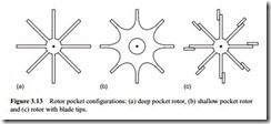
There are three rotor pocket configurations in widespread use, and these are shown in Figure 3.13. The most common type has deep pockets and hence maximum volumetric displacement. This is more suited to the handling of free flowing materials. Type (b) has shallow, rounded pockets and so its volumetric capacity is reduced. This configuration is generally used with the more cohesive types of material that tend to stick in deep pockets. Blade tips are often employed, and a sketch of such a rotor is given in Figure 3.13c). Many of these blade tips are adjustable to maintain operating efficiency. They can be made of resilient, spark-proof, flexible or abrasion resistant materials.
The rotor clearance can have a significant effect on valve performance, and in an attempt to minimise the effect of the leakage on the feed rate, manufacturers make these clearances as small as possible. Clearances on new valves are typically of the order of 0.075–0.15 mm. Clearances smaller than this would add considerably to the cost of manu- facture and may even lead to binding in the housing due to deflection of the rotor, or movement within the bearings, when subject to the applied pressure gradient in positive pressure applications.
The fitting of flexible elastomer/polymer wipers to the rotor blades, such that they are in sliding contact with the housing, is quite common. This approach, however, is generally limited to low pressure applications, typically up to about 0.25 bar gauge, since the leakage at pressure gradients greater than this can deflect the wipers and so lose their advantage.
The number of blades on the rotor will determine the number of blade labyrinth seals that the air must pass before escaping from the system. From an air loss point of view, therefore, a ten-bladed rotor would be specified for applications with pressure
differentials from 0.5 to 1.0 bar. Eight-bladed rotors are commonly used in applica- tions with pressure differentials up to 0.5 bar, and six-bladed rotors where the pressure differential is below 0.2 bar.
There is obviously a practical limitation to the number of blades that can be used in a rotor when handling a given material. The number is largely dependent upon the material itself, since increasing the number of blades decreases the angle between them. A decrease in this angle is sufficient with some materials to prevent if from being discharged when presented to the outlet port and is certainly inappropriate for cohesive materials.
Material feed rate
The feed rate of a rotary valve is directly proportional to the displacement volume of the rotor and its rotational speed. The displacement volume is simply the pocket size or volume multiplied by the number of rotor pockets. If a mass flow rate of material is required this must then be multiplied by the bulk density of the material. The constant of proportionality here is the volumetric or filling efficiency of the rotary valve:
where m·p is the mass flow rate of material (tonne/h); V, the volume of pocket (m3); n, the number of rotor pockets (1/rev); N, the rotational speed (rev/min); pb, the bulk density of material (kg/m3) and Y the filling efficiency (–).
Pocket filling efficiency
If air leakage impedes material flow, the pockets will not fill completely and so the volumetric efficiency will be reduced. Air leakage may also have the effect of reduc- ing the bulk density of the material, for with some materials the fluidized bulk density can be very much lower than the ‘as poured’ bulk density. It should be noted that, because of air leakage, the volumetric efficiency of a rotary valve when feeding a nega- tive pressure system will generally be much greater than when feeding a positive pres- sure system.
Feed rate control
As the rotary valve is a positive displacement device, feed rate control can be achieved quite simply by varying the speed of the rotor. Although the above approach might suggest that feed rate increases continually with rotor speed, there are in practice a number of factors that tend to reduce the feed rate below this maximum.
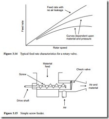
The pocket filling efficiency of a rotary valve, for example, is a function of rotor speed, for at increased speed the time available for pocket filling reduces. Up to a speed of about 20 rev/min the filling efficiency is reasonably constant, but above this speed it starts to decrease at an increasing rate. The situation is illustrated in Figure 3.14. There is also a lower limit on speed because of the problems associated with the low frequency
pulsations caused by pocket emptying. Thus there is a limit on feed rate with any given rotary valve, but they do come in a very wide range of sizes to meet almost any duty.


