Air receivers and compressor control
An air receiver is used to store high pressure air from the compressor. Its volume reduces pressure fluctuations arising from changes in load and from compressor switching.
Air coming from the compressor will be warm (if not actually hot!) and the large surface area of the receiver dissipates this heat to the surrounding atmosphere. Any moisture left in the air from the compressor will condense out in the receiver, so outgoing air should be taken from the receiver top.
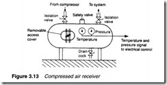
Figure 3.13 shows essential features of a receiver. They are usually of cylindrical construction for strength, and have a safety relief valve to guard against high pressures arising from failure of the pressure control scheme. Pressure indication and, usually, temperature indication are provided, with pressure switches for control of pressure and high temperature switches for remote alarms.
A drain cock allows removal of condensed water, and access via a manhole allows cleaning. Obviously, removal of a manhole cover is hazardous with a pressurised receiver, and safety routines must be defined and followed to prevent accidents.
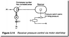
Control of the compressor is necessary to maintain pressure in the receiver. The simplest method of achieving this is to start the compressor when receiver pressure falls to some minimum pressure, and stop the compressor when pressure rises to a satisfactory level again, as illustrated in Figure 3.14. In theory two pressure switches are required (with the motor start pressure lower than the motor stop pressure) but, in practice, internal hysteresis in a typical switch allows one pressure switch to be used. The pressure in the receiver cycles between the start and stop pressure settings.
In Figure 3.15 another method of pressure control is shown, where the compressor runs continuously and an exhaust valve is fitted to the compressor outlet. This valve opens when the required pressure is reached. A non-return valve prevents air returning from the receiver. This technique is known as exhaust regulation.
Compressors can also be controlled on the inlet side. In the example of Figure 3.16, an inlet valve is held open to allow the compressor to operate, and is closed when the air receiver has
reached the desired pressure, (the compressor then forms a near vacuum on its inlet side).
The valves in Figure 3.15 and 3.16 can be electrically-operated solenoid valves controlled by pressure switches, or can be pneumatic valves controlled directly by receiver pressure.
The control method is largely determined by flow rates from receiver to the load(s) and the capacity of the compressor. If the compressor has significant spare capacity, for example, start/stop control is commonly used.
If compressor capacity and load requirements are closely matched, on the other hand, short start/stop cycling may cause pre mature wear in the electrical starter for the compressor motor. In this situation, exhaust or inlet regulation is preferred.
Air receiver size is determined by load requirements, compressor capacity, and allowable pressure deviations in the receiver. With the compressor stopped, Boyle’s law (expression 1.17) gives the pressure decay for a given volume of air delivered from a given receiver at a known pressure. For example, if a receiver of 10 cubic metres volume and a working pressure of 8 bar delivers 25 cubic metres of air (at STP) to a load, pressure in the receiver falls to approximately 5.5 bar.
With the compressor started, air pressure rises at a rate again given by expression 1.17 (with the air mass in the receiver being increased by the difference between the air delivered by the compressor and that removed by the load).
These two calculations give the cycle time of the compressor when combined with settings of the cut-in and drop-out pressure switches. If this is unacceptably rapid, say less than a few minutes, then a larger receiver is required. Manufacturers of pneumatic equipment provide nomographs which simplify these calculations.
An air receiver is a pressure vessel and as such requires regular visual and volumetric pressure tests. Records should be kept of the tests.


