■ THE LOG MEAN TEMPERATURE DIFFERENCE METHOD
Earlier, we mentioned that the temperature difference between the hot and cold fluids varies along the heat exchanger, and it is convenient to have a mean temperature difference /},Tm for use in the relation Q = UAs /},Tm.
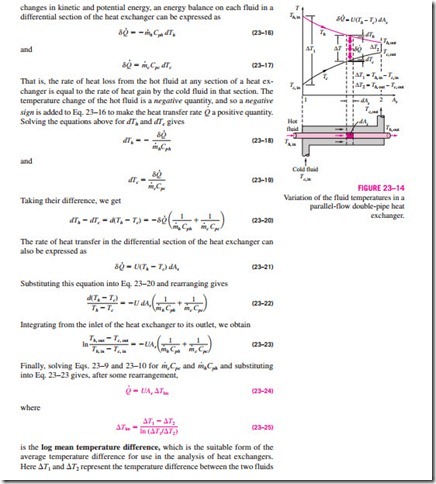
In order to develop a relation for the equivalent average temperature difference between the two fluids, consider the parallel-flow double-pipe heat ex- changer shown in Fig. 23–14. Note that the temperature difference /},T between the hot and cold fluids is large at the inlet of the heat exchanger but decreases exponentially toward the outlet. As you would expect, the temperature of the hot fluid decreases and the temperature of the cold fluid increases along the heat exchanger, but the temperature of the cold fluid can never exceed that of the hot fluid no matter how long the heat exchanger is.
Assuming the outer surface of the heat exchanger to be well insulated so that any heat transfer occurs between the two fluids, and disregarding any
changes in kinetic and potential energy, an energy balance on each fluid in a differential section of the heat exchanger can be expressed as
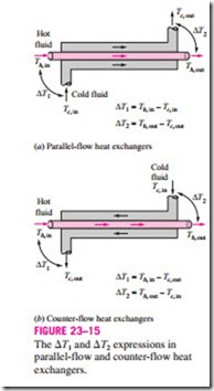
at the two ends (inlet and outlet) of the heat exchanger. It makes no difference which end of the heat exchanger is designated as the inlet or the outlet (Fig. 23–15).
The temperature difference between the two fluids decreases from /},T1 at the inlet to /},T2 at the outlet. Thus, it is tempting to use the arithmetic mean temperature /},Tam = 1 (/},T1 + /},T2) as the average temperature difference. The logarithmic mean temperature difference /},Tlm is obtained by tracing the ac- tual temperature profile of the fluids along the heat exchanger and is an exact representation of the average temperature difference between the hot and cold fluids. It truly reflects the exponential decay of the local temperature difference.
Note that /},Tlm is always less than /},Tam. Therefore, using /},Tam in calculations instead of /},Tlm will overestimate the rate of heat transfer in a heat ex- changer between the two fluids. When /},T1 differs from /},T2 by no more than 40 percent, the error in using the arithmetic mean temperature difference is less than 1 percent. But the error increases to undesirable levels when /},T1 differs from /},T2 by greater amounts. Therefore, we should always use the logarithmic mean temperature difference when determining the rate of heat transfer in a heat exchanger.
Counter-Flow Heat Exchangers
The variation of temperatures of hot and cold fluids in a counter-flow heat exchanger is given in Fig. 23–16. Note that the hot and cold fluids enter the heat exchanger from opposite ends, and the outlet temperature of the cold fluid in this case may exceed the outlet temperature of the hot fluid. In the limiting case, the cold fluid will be heated to the inlet temperature of the hot fluid. However, the outlet temperature of the cold fluid can never exceed the inlet temperature of the hot fluid, since this would be a violation of the second law of thermodynamics.
The relation already given for the log mean temperature difference is developed using a parallel-flow heat exchanger, but we can show by repeating the analysis for a counter-flow heat exchanger that is also applicable to counter- flow heat exchangers. But this time, /},T1 and /},T2 are expressed as shown in Fig. 23–15.
For specified inlet and outlet temperatures, the log mean temperature difference for a counter-flow heat exchanger is always greater than that for a parallel-flow heat exchanger. That is, /},Tlm, CF > /},Tlm, PF, and thus a smaller surface area (and thus a smaller heat exchanger) is needed to achieve a specified heat transfer rate in a counter-flow heat exchanger. Therefore, it is common practice to use counter-flow arrangements in heat exchangers.
In a counter-flow heat exchanger, the temperature difference between the hot and the cold fluids will remain constant along the heat exchanger when the heat capacity rates of the two fluids are equal (that is, /},T = constant when Ch = Cc or mhCph = mcCpc). Then we have /},T1 = /},T2, and the last log mean temperature difference relation gives /},Tlm = 0 , which is indeterminate.
It can be shown by the application of l’Hôpital’s rule that in this case we have as expected.
A condenser or a boiler can be considered to be either a parallel- or counter flow heat exchanger since both approaches give the same result.
Multipass and Cross-Flow Heat Exchangers: Use of a Correction Factor
The log mean temperature difference /},Tlm relation developed earlier is limited
to parallel-flow and counter-flow heat exchangers only. Similar relations are also developed for cross-flow and multipass shell-and-tube heat exchangers, but the resulting expressions are too complicated because of the complex flow conditions.
In such cases, it is convenient to relate the equivalent temperature dif- ference to the log mean temperature difference relation for the counter-flow case as
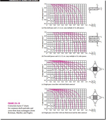
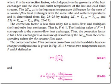
where F is the correction factor, which depends on the geometry of the heat exchanger and the inlet and outlet temperatures of the hot and cold fluid streams. The /},Tlm, CF is the log mean temperature difference for the case of a counter-flow heat exchanger with the same inlet and outlet temperatures and is determined from Eq. 23–25 by taking /},Tl = Th, in – Tc, out and The correction factor is less than unity for a cross-flow and multipass shell-and-tube heat exchanger. That is, F :s 1. The limiting value of F = 1 corresponds to the counter-flow heat exchanger. Thus, the correction factor F for a heat exchanger is a measure of deviation of the /},Tlm from the corresponding values for the counter-flow case.
The correction factor F for common cross-flow and shell-and-tube heat ex- changer configurations is given in Fig. 23–18 versus two temperature ratios P and R defined as
where the subscripts 1 and 2 represent the inlet and outlet, respectively. Note that for a shell-and-tube heat exchanger, T and t represent the shell- and tube-side temperatures, respectively, as shown in the correction factor charts. It makes no difference whether the hot or the cold fluid flows through the shell or the tube. The determination of the correction factor F requires the availability of the inlet and the outlet temperatures for both the cold and hot fluids.
Note that the value of P ranges from 0 to 1. The value of R, on the other hand, ranges from 0 to infinity, with R = 0 corresponding to the phase-change (condensation or boiling) on the shell-side and R → oc to phase-change on the tube side. The correction factor is F = 1 for both of these limiting cases. Therefore, the correction factor for a condenser or boiler is F = 1, regardless of the configuration of the heat exchanger.