loadIng valves
Expression 2.2 shows that allowing excess fluid from a pump to return to the tank by a pressure relief valve is wasteful of energy and can lead to a rapid rise in temperature of the fluid as the wasted energy is converted to heat. It is normally undesirable to start and stop the pump to match load requirements, as this causes shock loads to pump, motor and couplings.
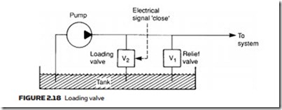
In Figure 2.18, valve V1 is a normal pressure relief valve regulating pres- sure and returning excess fluid to the tank as described in earlier sections. The additional valve V2 is opened or closed by an external electrical or hydraulic signal. With valve V2 open, all the pump output flow is returned to the tank at low pressure with minimal energy cost.
When fluid is required in the system the control signal closes valve V2, pres- sure rises to the setting of valve V1, and the system performs as normal. Valve V2 is called a pump loading or a pump unloading valve according to the interpretation of the control signal sense.
Pump Problems
Cavitation is the formation of vapor bubbles in a flowing liquid. When the bub- ble rapidly collapses, it produces an intense shock wave which rapidly erodes contact surfaces. If a pump suffers from cavitation it will be very noisy and suf-
fer from early failure. Causes of cavitation are high-viscosity fluid, low temperature, pump overspeed (e.g. wrong motor fitted), inlet line too small or blocked inlet strainer.
Aeration occurs when air is drawn into the fluid leading to spongy imprecise operation. Possible causes are worn pump shaft seal, low oil level (allowing a vortex to form), return line above liquid level entrapping air or leak on pump inlet line allowing air to be drawn in. Leaks on the pressure side of the pump do not, generally, cause aeration.
No pump is 100% efficient and all suffer from some degree of leakage. Surprisingly a pump can suffer a major loss of displacement and still work satisfactorily, as discussed in Chapter 9. Leakage generally results in low speed rather than complete failure. Fault finding is simplified if a flow/pressure sensor (such as the UCC System 20) is fitted between the pump and the relief valve.
fIlters
Dirt in a hydraulic system causes sticking valves, failure of seals and premature wear. Even particles of dirt as small as 20 mm can cause damage (1 micron is one millionth of a meter; the naked eye is just able to resolve 40 mm). Filters are used to prevent dirt entering the vulnerable parts of the system, and are generally specified in microns or meshes per linear inch (sieve number).
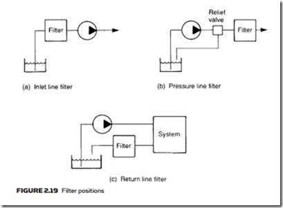
Inlet lines are usually fitted with strainers inside the tank, but these are coarse wire mesh elements only suitable for removing relatively large metal particles and similar contaminants. Separate filters are needed to remove finer particles and can be installed in three places, as shown in Figure 2.19a–c.
Inlet line filters protect the pump, but must be designed to give a low pres- sure drop or the pump will not be able to raise fluid from the tank. Low pressure drop implies a coarse filter or a large physical size.
Pressure line filters placed after the pump protect valves and actuators and can be finer and smaller. They must, however, be able to withstand full system operating pressure. Most systems use pressure line filtering.
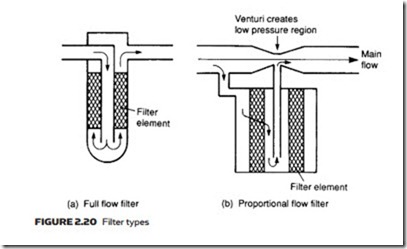
Return line filters may have a relatively high pressure drop and can, consequently, be very fine. They serve to protect pumps by limiting the size of particles returned to the tank. These filters only have to withstand a low pressure. Filters can also be classified as full or proportional flow. In Figure 2.20a, all flow passes through the filter. This is obviously efficient in terms of filtra- tion, but incurs a large pressure drop. This pressure drop increases as the filter becomes polluted, so a full flow filter usually incorporates a relief valve which cracks when the filter becomes unacceptably blocked. This is purely a safety feature, though, and the filter should, of course, have been changed before this state was reached as dirty unfiltered fluid would be passing round the system.
In Figure 2.20b, the main flow passes through a venturi, creating a localized low- pressure area. The pressure differential across the filter element draws a proportion of the fluid through the filter. This design is accordingly known as a proportional flow filter, as only a proportion of the main flow is filtered. It is characterized by a low pressure drop, and does not need the protection of a pressure relief valve.
Pressure drop across the filter element is an accurate indication of its cleanli- ness, and many filters incorporate a differential pressure meter calibrated with a green (clear), amber (warning), red (change overdue) indicator. Such types are called indicating filters.
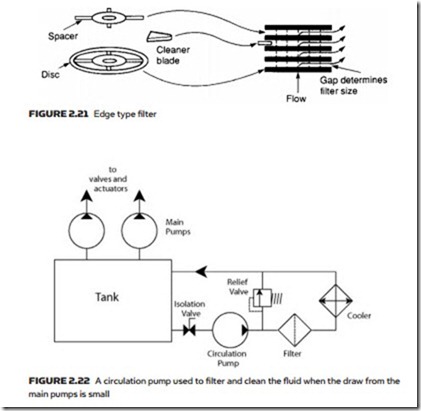
Filtration material used in a filler may be mechanical or absorbent. Me- chanical filters are relatively coarse, and utilize fine wire mesh or a disc/screen arrangement as shown in the edge type filter of Figure 2.21. Absorbent filters are based on porous materials such as paper, cotton or cellulose. Filtration size
n an absorbent filter can be very small as filtration is done by pores in the mate- rial. Mechanical filters can usually be removed, cleaned and re-fitted, whereas absorbent filters are usually replaceable items.
In many systems where the main use is the application of pressure the actual draw from the tank is very small, reducing the effectiveness of pressure and return line filters. Here a separate circulating pump may be used as shown in Figure 2.22 to filter and cool the oil. The running of this pump is normally a pre- condition for starting the main pumps. The circulation pump should be sized to handle the complete tank volume every 10–15 minutes.
Note the pressure relief valve – this is included to provide a route back to the tank if the filter or cooler is totally blocked. In a real-life system additional hand isolation and non-return valves would be fitted to permit changing the filter or cooler with the system running. Limit switches and pressure switches would also be included to signal to the control system that the hand isolation valves are open and the filter is clean.


