Vertical pipelines
At least one section of vertically up pipeline will feature in the majority of pipeline systems, if only to elevate the material into a reception vessel at the end of the pipeline. In some cases the length of the vertically up section of pipeline can be 500 m or more, as in mining and shaft sinking operations. Vertically down sections may also occur if the pipeline is routed around some obstacle in its path. In the mining industry, materials such as fly ash and cement are often conveyed vertically down mine shafts to under- ground workings. In order to determine the influence of vertical sections in a pipeline it is generally necessary to use pressure tappings along the length of the section to be considered, as discussed in Section 10.6. By this means, data can be obtained for the vertical sections in isolation from any bends and the rest of the pipeline [5–7].
Conveying vertically up
In the majority of pneumatic conveying system pipelines the proportion of horizontal conveying is very much greater than that of vertical conveying. A scaling parameter, therefore, is required in terms of an equivalent length of straight horizontal pipeline.
Scaling parameter
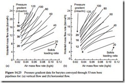
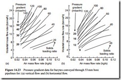
Data for the vertically upward conveying of barytes in a 53 mm bore pipeline is pre- sented in Figure 14.23a. Similar data for both fly ash and cement, conveyed vertically upwards, was presented earlier in Figures 11.13 and 11.14. These are all conveying characteristics for the material in terms of pressure gradient. Similar data for the barytes conveyed in a horizontal pipeline of 53 mm bore was presented in Figure 11.15. This is now reproduced in Figure 14.23b to be alongside the vertical data for bartyes so that a direct visual comparison of the two can be made.
With these two sets of data in Figure 14.23, a scaling parameter can be determined simply by evaluating the ratio between the two sets of data. In order to provide the necessary comparison of the vertical and horizontal 53 mm bore pipeline conveying characteristics, a rectangular grid was placed on both sets of curves and pressure gradient values were noted at every grid point.
In Figure 14.24a the value of the ratios of the vertical line pressure gradient divided by the horizontal line pressure gradient, determined for every grid point, are presented.
They are also plotted on a graph of material flow rate against air mass flow rate and, from the various lines of constant solids loading ratio superimposed, it can be seen that the relationship obtained covers a very wide range of conveying conditions. A similar analysis was carried out with a fine grade of fly ash, which is presented in Figure 14.24b, and this produced almost identical results.
It will be noticed that there is little variation in this ratio from minimum to maximum values of conveying air velocity, and from minimum to maximum values of solids loading ratio. The only deviation from a mean value of about 2.0 would appear to be at the two extreme limits of the pressure gradient curves, where the data is least reliable.
This, therefore, shows that the pressure drop in vertically up conveying is approxi- mately double that in horizontal conveying, for given conveying conditions, over the entire range of conveying conditions. The scaling parameter, therefore, for vertically upward conveying is simply two, so that the length of vertically upward sections of pipeline should be doubled to give the equivalent length of straight horizontal pipeline.
Conveying vertically down
Similar data for the conveying of barytes vertically down in a 53 mm bore pipeline is presented in Figure 14.25. Similar data for a fine grade of fly ash was shown earlier in Figure 11.13a. These both show a very much more complex pattern, with a pressure drop occurring for dilute phase flows and a pressure recovery for dense phase flows.
For short vertically down sections of pipe, in an otherwise long pipeline, it would be suggested that the length of such sections could be disregarded, if they are no more than a few metres, although connecting bends must always be included. If the verti- cally down section of pipeline is of any significant length, it must be taken into account. If the material is conveyed in dilute phase there will be a pressure drop, although of a lower value than for horizontal flow. If the material is conveyed in dense phase flow there could be a significant pressure recovery and it would be essential to take this into account in the pipeline design.
Inclined pipelines
The recommendation with regard to pipeline orientation is generally that pipelines should run either vertically up or horizontal, and that inclined sections of pipeline should
be avoided, even if their use means that the pipeline length is reduced. Two separate factors have to be taken into account in the use of inclined sections of pipeline. One is the influence on the minimum value of conveying air velocity and the other is the effect on conveying line pressure drop.
Minimum conveying air velocity
The vast majority of data presented here has been for horizontal pipeline, with particular concern for dilute phase suspension flow. For a material with a minimum conveying air velocity of 15 m/s for horizontal flow, the corresponding minimum value for flow in a vertically up pipeline will be lower. In the vast majority of pipelines it is just not practically possible to benefit from this, since material is generally fed into horizontal sections of pipeline. In addition, vertical sections of pipeline are short in comparison to horizontal pipeline, and the velocity of the air automatically increases along the length of the pipeline as the pressure reduces.
In horizontal pipeline, as the conveying air velocity is reduced, particles begin to settle on the bottom of the pipeline and form a layer. This settled layer will reduce the effective cross sectional area of the pipeline and so increase the conveying air velocity, which can lead to a degree of stability. There will, however, with a further reduction in velocity, be a tendency to duning of the layer and if this is swept up to fill the pipe bore then the pipeline is likely to block, particularly at a bend.
In vertical pipelines, particles will tend to drop out of suspension in the boundary layer near to the wall first, where the conveying air velocity is lowest. These particles, however, will initially be re-entrained in the upward flow since there is no surface on which they can settle.
In pipeline inclined upwards, saltating particles will drop to the bottom of the pipeline. Due to the incline they will tend to be more mobile and so form dunes more readily. As a consequence the minimum conveying air velocity for pipeline inclined
upwards tends to be higher than that for horizontal pipeline. Such an inclined section well along the length of a pipeline is not likely to be a problem in this respect since the conveying air velocity will have increased to a much higher velocity. This is not so much of a problem in pipelines that slope downwards.
Pipeline pressure gradient
The pressure gradient in vertically upward flow is significantly greater than that for horizontal pipeline, as was illustrated in Figures 14.23 and 14.24. A colleague of the author undertook research into the influence of pipeline inclination and some of his data on this issue is presented in Figure 14.26 [8].
The work was undertaken with a 100 m long pipeline of 81 mm bore, having a central section 8 m long that could be conveniently adjusted to provide inclinations ranging from -20° to +90°. The test work reported was undertaken with 3 mm poly- mer pellets. In Figure 14.26a the results are presented in terms of the difference between the total pressure gradient for an inclined pipe and that for a horizontal pipe, while in Figure 14.26b the results are in terms of a normalized pressure gradient, which is the ratio of the pressure gradient for a particular angle of inclination divided by that for the horizontal. Solids loading ratios of 5, 10 and 20 were considered. This shows quite clearly that pipelines inclined upwards should be avoided if at all possible.


