LIQUIDS IN MOTION (HYDRAULICS)
In the operation of fluid power systems, there must be flow of fluid. The amount of flow will vary from system to system. To understand fluid power systems, it is necessary to understand some of the characteristics of liquids in motion.
Liquids in motion have characteristics different from those of liquids at rest. Frictional resistances within the fluid, viscosity, and inertia contribute to these differences. Inertia, which
means the resistance a mass offers to being set in motion, will be discussed later in this section. There are other relationships of liquids in motion with which you must become familiar. Among these are volume and velocity of flow; flow rate and speed; laminar and turbulent flow; and more importantly, the force and energy changes that occur in flow.
VOLUME AND VELOCITY OF FLOW
The volume of a liquid passing a point in a given time is known as its volume of flow or flow rate. The volume of flow is usually expressed in gallons per minute (gpm) and is associated with the relative pressures of the liquid, such as 5 gpm at 40 psig. The velocity of flow or velocity of the fluid is defined as the average speed at which the fluid moves past a given point. It is usually expressed in feet per minute (fpm) or inches per second (ips). Velocity of flow is an important consideration in sizing the hydraulic piping and other system components.
Volume and velocity of flow must be considered together. With other conditions unaltered, the velocity of flow increases as the cross-section or size of the pipe decreases, and the velocity of flow decreases as the cross-section or pipe size increases. For example, the velocity of flow is slow at wide parts, yet the volume of liquid passing each part of the stream is the same.
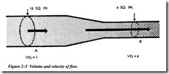
In Figure 2-5, if the cross-sectional area of the pipe is 16 square inches at point A and 4 square inches at point B, we can calculate the relative velocity of flow using the flow equation
Q = vA
where Q is the volume of flow, v is the velocity of flow, and A is the cross-sectional area of the liquid. Since the volume of flow at point A, Q 1 , is equal to the volume of
flow at point B, Q2,we can use this equation to determine the ratio of the velocity of flow at point A, v 1, to the velocity of flow at point B, v2.
From Figure 2-5:
A 1 = 16 square inches, A2 = 4 square inches Substituting: 16v1 = 4v2 or v2 = 4v 1
Therefore, the velocity of flow at point B is four times greater than the velocity of flow at point A.
VOLUME OF FLOW AND SPEED
When you consider the cylinder volume that must be filled and the distance that the piston must travel, you can relate the volume of flow to the speed of the piston. The volume of the cylinder is found by multiplying the piston area by the length the piston must travel. This length is known as stroke.
Suppose you have determined that two cylinders have the same volume and that one cylinder is twice as long as the other. In this case, the cross-sectional area of the longer tube will be half of the cross-sectional area of the other tube. If fluid is pumped into each cylinder at the same rate, both pistons will reach their full travel at the same time. However, the piston in the smaller cylinder must travel twice as fast because it has twice as far to go. There are two ways of controlling the speed of the piston: (1) by varying the size of the cylinder and (2) by varying the volume of flow (gpm) to the cylinders.

