Hydraulic accumulators
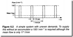
In a simple hydraulic system, the pump size (delivery rate and hence motor power) is determined by the maximum requirements of the actuators. In Figure 6.2 a system operates intermittently at a
pressure of between 150 and 200 bar, needing a flow rate of 100 1 min-1 for 10 s at a repetition rate of 1 minute. With a simple system (pump, pressure regulator and loading valve) this requires a 200 bar, 100 1 min-1 pump (driven by about a 50 hp motor) which spends around 85% of its time unloading to tank.
In Figure 6.3a a storage device called an accumulator has been added to the system. This can store, and release, a quantity of fluid at the required system pressure. In many respects it resembles the operation of a capacitor in an electronic power supply.
The operation is shown in Figure 6.3b. At time A the system is turned on, and the pump loads causing pressure to rise as the fluid is delivered to the accumulator via the non-return valve V3. At time B, working pressure is reached and a pressure switch on the accumulator causes the pump to unload. This state is maintained as non return valve V3 holds the system pressure.
The actuator operates between times C and D. This draws fluid from the accumulator causing a fall of system pressure. The pressure switch on the accumulator puts the pump on load again but it takes until time E before the accumulator is charged ready for the next actuator movement at time F.
An accumulator reduces pump requirements. The original system required a 100 1 min-1 pump. With an accumulator, however, a pump only needs to provide 17 1 min-1 (that is, 100 1 min-1 for 10 sees every minute). Pump size, and hence motor size, have been reduced by a factor of six with obvious cost and space savings, plus gains in ancillary equipment such as motor starters and cabling. There is no gain in the energy used; with the simple system a 50 hp motor loads for 17% of the time, with an accumulator a 10 hp motor loads for about 90% of the time.
Most accumulators operate by compressing a gas (although older and smaller accumulators may work by compressing a spring or lifting a weight with a cylinder). The most common form is the gas filled bladder accumulator shown in Figure 6.4. Gas is precharged to some pressure with the accumulator empty of fluid when the whole of the accumulator is filled with gas. A poppet valve at the accumulator base prevents the bladder extruding out into the p1pmg.
Accumulators are sized by Boyle’s law and a knowledge of the demands of the actuators. For the example system of Figure 6.2,
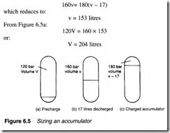
assuming a precharge of 120 bar, a charged accumulator pressure of 180 bar and a fall to a pressure to 160 bar during the removal of 17 litres of fluid: let V be volume of accumulator. This gives us the three states illustrated in Figure 6.5 to which Boyle’s law can be applied to find the required accumulator volume.
From Figure 6.5b and c using Boyle’s law:
Hence an accumulator of around 250 litres is required, with a precharge of 120 bar and a pressure switch set at 180 bar.
Accumulators can also be used to act as ‘buffers’ on a system to absorb shocks and snub pressure spikes. Again the accumulator acts in similar manner to a capacitor in an electronic circuit.
An accumulator, however, brings an additional danger into the system, as it is possible for high pressures to exist in the circuit even though the pump has been stopped. If a coupling is opened under these circumstances the accumulator discharges all its fluid at working pressure. The author speaks from personal experience of having committed this cardinal sin and being covered in oil for his mistake!
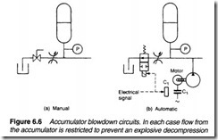
Extreme care should therefore be taken when working on circuits with accumulators. Normally a manual or automatic blowdown valve is included to allow the accumulator pressure to be released. The pressure gauge should be observed during blowdown and no work undertaken until it is certain all pressure has been released.
Figure 6.6 shows typical blowdown circuits.
Once a system has warmed up, a quick check can be made on the state of an accumulator with the flat of the hand. There should always be a significant temperature difference between the gas and the hydraulic oil and the oil/gas split can be detected by the temperature change on the body of the accumulator. If the whole body is the same temperature something has gone severely wrong with the gas bladder.
An accumulator is a pressurised vessel and as such requires certification if it contains more than 250 bar.litres. It will require a recorded expert visual inspection every five years and a full volumetric pressure test every ten years.


