GENERAL CONSIDERATIONS FOR PIPE FLOW
Liquid or gas flow through pipes or ducts is commonly used in practice in heating and cooling applications. The fluid in such applications is forced to flow by a fan or pump through a conduit that is sufficiently long to accomplish the desired heat transfer.
The general aspects of flow in pipes were considered in Chap. 14. The Reynolds number for flow through a pipe of inside diameter D was defined as
where ‘V is the mean velocity and u = m/r is the kinematic viscosity of the fluid. Under most conditions, the flow in a pipe is said to be laminar for Re < 2300, turbulent for Re > 4000, and transitional in between.
When a fluid is heated or cooled as it flows through a tube, the temperature of the fluid at any cross section changes from Ts at the surface of the wall to some maximum (or minimum in the case of heating) at the tube center. In fluid flow it is convenient to work with an average or mean temperature Tm that remains uniform at a cross section. Unlike the mean velocity, the mean
temperature Tm will change in the flow direction whenever the fluid is heated or cooled.
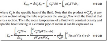
The value of the mean temperature Tm is determined from the requirement that the conservation of energy principle be satisfied. That is, the energy trans- ported by the fluid through a cross section in actual flow must be equal to the energy that would be transported through the same cross section if the fluid were at a constant temperature Tm. This can be expressed mathematically as (Fig. 19–19)
Note that the mean temperature Tm of a fluid changes during heating or cooling. Also, the fluid properties in internal flow are usually evaluated at the bulk mean fluid temperature, which is the arithmetic average of the mean temperatures at the inlet and the exit. That is, Tb = (Tm, i + Tm, e)/2.
Thermal Entrance Region
The development of the velocity boundary layer was discussed in Chap. 14.
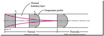
Now consider a fluid at a uniform temperature entering a circular tube whose surface is maintained at a different temperature. This time, the fluid particles in the layer in contact with the surface of the tube will assume the surface temperature. This will initiate convection heat transfer in the tube and the development of a thermal boundary layer along the tube. The thickness of this boundary layer also increases in the flow direction until the boundary layer reaches the tube center and thus fills the entire tube, as shown in Fig. 19–20.
The region of flow over which the thermal boundary layer develops and reaches the tube center is called the thermal entrance region, and the length of this region is called the thermal entry length Lt. Flow in the thermal en- trance region is called thermally developing flow since this is the region where
the temperature profile develops. The region beyond the thermal entrance region in which the dimensionless temperature profile expressed as (Ts – T)/ (Ts – Tm) remains unchanged is called the thermally fully developed region. The region in which the flow is both hydrodynamically and thermally developed and thus both the velocity and dimensionless temperature profiles re- main unchanged is called fully developed flow. That is,
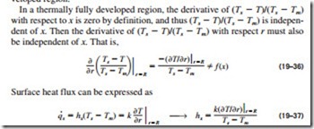
The friction factor is related to the shear stress at the surface, which is related to the slope of the velocity profile at the surface. Noting that the velocity profile remains unchanged in the hydrodynamically fully developed region, the friction factor also remains constant in that region. A similar argument can be given for the heat transfer coefficient in the thermally fully developed region.
which, from Eq. 19–36, is independent of x. Thus we conclude that in the thermally fully developed region of a tube, the local convection coefficient is constant (does not vary with x). Therefore, both the friction and convection coefficients remain constant in the fully developed region of a tube.
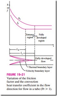
Note that the temperature profile in the thermally fully developed region may vary with x in the flow direction. That is, unlike the velocity profile, the temperature profile can be different at different cross sections of the tube in the developed region, and it usually is. However, the dimensionless temperature profile already defined remains unchanged in the thermally developed region when the temperature or heat flux at the tube surface remains constant. During laminar flow in a tube, the magnitude of the dimensionless Prandtl number Pr is a measure of the relative growth of the velocity and thermal boundary layers. For fluids with Pr = 1, such as gases, the two boundary lay- ers essentially coincide with each other. For fluids with Pr � 1, such as oils, the velocity boundary layer outgrows the thermal boundary layer. As a result, the hydrodynamic entry length is smaller than the thermal entry length. The opposite is true for fluids with Pr � 1 such as liquid metals.
Consider a fluid that is being heated (or cooled) in a tube as it flows through it. The friction factor and the heat transfer coefficient are highest at the tube inlet where the thickness of the boundary layers is zero, and decrease gradually to the fully developed values, as shown in Fig. 19–21. Therefore, the pressure drop and heat flux are higher in the entrance regions of a tube, and the effect of the entrance region is always to enhance the average friction and heat transfer coefficients for the entire tube. This enhancement can be significant for short tubes but negligible for long ones.
In laminar flow, the hydrodynamic and thermal entry lengths are given approximately as [see Kays and Crawford (1993) and Shah and Bhatti (1987)].
The hydrodynamic entry length is much shorter in turbulent flow, as ex- pected, and its dependence on the Reynolds number is weaker. It is 11D at Re = 10,000, and increases to 43D at Re = 105. In practice, it is generally agreed that the entrance effects are confined within a tube length of 10 diameters, and the hydrodynamic and thermal entry lengths are approximately taken to be
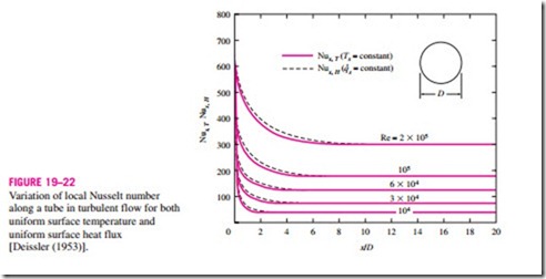
The variation of local Nusselt number along a tube in turbulent flow for both uniform surface temperature and uniform surface heat flux is given in Fig. 19–22 for the range of Reynolds numbers encountered in heat transfer equipment. We make these important observations from this figure:
• The Nusselt numbers and thus the convection heat transfer coefficients are much higher in the entrance region.
• The Nusselt number reaches a constant value at a distance of less than 10 diameters, and thus the flow can be assumed to be fully developed for x > 10D.
• The Nusselt numbers for the uniform surface temperature and uniform surface heat flux conditions are identical in the fully developed regions, and nearly identical in the entrance regions. Therefore, Nusselt number
is insensitive to the type of thermal boundary condition, and the turbulent flow correlations can be used for either type of boundary condition.
Precise correlations for the friction and heat transfer coefficients for the en- trance regions are available in the literature. However, the tubes used in practice in forced convection are usually several times the length of either entrance region, and thus the flow through the tubes is often assumed to be fully developed for the entire length of the tube. This simplistic approach gives reason- able results for long tubes and conservative results for short ones.

