COMPRESSOR INSTALLATION
A compressor installation may be centralised where all the compressors needed are housed in a single compressor plant; or decentralised where individual compressors are located near the points of use. A centralised installation can show greater cost-effectiveness as well as making it easier to optimize intake conditions and silencing. There are a few situations where decentralised stations are to be preferred:- if there is a requirement for different working pressures in some parts of the factory; where warm air is required, eg for pneumatic operation of forging tools; where part of the air is required at a considerable distance from the main installation and the pressure drop of a long line would be unacceptable.
Modern practice with centralised installations employs individual compressors with their associated ancillary equipment as completely separate units. It is then possible to shut down a single compressor for maintenance and leave the remainder operating. Most factories have a fluctuating demand for compressed air during the working day, so there is no need to keep all units running when only a proportion are needed to supply the factory. Even off-load, a compressor consumes a considerable amount of power so it makes sense to have the smallest number running at any one time. With modern control equipment compressors can be brought on stream rapidly when the demand for extra air is sensed. A decision about the number of compressors to be installed depends primarily on the importance of continuity of production. Ifit is acceptable to work with a reduced air supply in the event of an unscheduled shut down, then two compressors each capable of 50% of the total requirement may be satisfactory. If a partial shut down is not permissible then a reserve supply must be available, so that three compressors each capable of 50% must be installed. Generally the larger the compressor, the more efficient it will be, so the number of separate units should be kept small, consistent with these considerations.
In assessing the capacity of a compressor installation, attention must be paid to leakage which is an inescapable feature of practically all pipe runs; 10% should normally be allowed for unless extra care is taken in the initial design. Further possible increases in capacity should also be allowed for.
Ideally a compressor should be located where it can induct clean, dry and cool air; this requires that the air intake should be placed on the shaded side of its building, well away from its cooling tower; there must be no possibility that the air intake can draw in inflammable vapours for example from paint spraying or petrol fumes. Although an inlet filter must be incorporated, a site should be chosen where dust particles are not readily drawn in. There is no need to put a heavier burden on the filter than absolutely necessary. A filter will only extract a percentage of the dust in the air (although it may be as much as 98%); the remaining abrasive particles can cause serious damage to the lubrication system.
Another primary consideration is that a compressor is inherently a noisy machine and unless specifically designed or treated for noise control, should be located in a ‘noisy’ area of the factory or workshop. In the case of a centralised installation it is generally desirable (and virtually necessary in the case of larger machines) to have the compressor in a separate well ventilated building room or chamber, inducting the air from outside of the building. Each compressor should have a separate air intake, and the pressure drop over the intake system should be kept low.
Basic treatment of the intake system is the fitting of an air intake filter of a suitable type and size to ensure that air reaching the compressor is clean ; and a separate air intake silencer to reduce intake noise which is the predominant noise-generator. Further noise treatment may have to be applied both to the machine itself and the room (eg the provision of adequate ventilation can establish noise paths which may then require treatment). Further information can be found in the chapter on Compressor Noise Reduction.
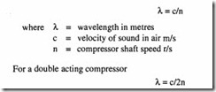
In the case of reciprocating compressors, the intake flow is pulsatory. This can aggravate noise problems if the intake pipe is of such a length that there is resonance with the pulsation frequency of the compressor. Apart from the noise problem, the intake flow can also be adversely affected. As a general rule the chance of resonance occurring is greatest when the intake pipe length corresponds to one-quarter or three-quarters of the pressure pulse wavelength (A.) which for a single-acting compressor is given by:
For dry air c = 20 -JT where T is the absolute temperature in K, which for an inlet temperature of l5°C equals 340 m/s. For a more accurate value, see the chapter on Properties of Air and Gases.
The intake lengths to be avoided are 0.1?A to 0.331. and 0.67A to 0.831..
High speed rotary compressors are comparatively pulsation-free and intake flow resonance is rarely a problem.
Compressor intake
The intake system must be designed with a low pressure drop in mind, that is with a limit on the air intake velocities. At the same time, intake flow should be smooth rather than
pulsating, as this will appreciably reduce intake noise and resonance effects.
Low pressure drop is ensured by sizing the intake pipes such that the flow velocity is no more than:
5 to 6 m/s in the case of single-acting compressors 6 to 7 rn/s in the case of double-acting compressors
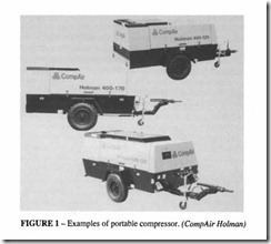
Combined with a venturi-type intake silencer these intake velocities can be increased by up to 10%. A typical arrangement is shown in Figure I.
Proper consideration must be given to the ventilation of the compressor house to dissipate the heat generated by the compressor and driver. This is particularly important in air-cooled units. With water-cooled compressors, or air-cooled compressors with water-cooled intercoolers, the amount of radiant heat to be dissipated is usually negligible since the majority of the heat is carried away by the cooling water.
Delivery line
Pressure drop in the discharge line does not materially affect the compressor efficiency, so the gas velocity can be 20 to 25 m/s. Pressure pulsations on the other hand can cause a considerable increase in compressor power as well as damage to the piping and valves. There are two ways of dealing with the problem of delivery line pulsations: tuning the pipe length between compressor delivery valve and the after-cooler; and inserting a pulsation
for heating adjacent premises. damper in the form of a small air receiver.
Energy recovery
With water-cooled compressors it is possible to recover a high proportion of the intake energy in the form of hot water which can be used for space heating, feed water for boilers, etc in a large factory. A typical system for heat recovery is shown in Figure 2. With air cooled compressors, the hot air leaving the intercooler and aftercooler can be directed to an adjacent room for space heating as in Figure 3.
Foundations
Installation is seldom a problem with compressors below a rating of 30 kW. Larger machines may need special foundations, the size and cost of such foundations increasing with compressor size, particularly in the case of reciprocating compressors with large out of-balance forces.
Some layouts are less likely to generate out of balance forces. ‘L’, ‘V’ or ‘W’ configurations are better than vertical or horizontal types. Dynamic compressors and rotary screws seldom require anything extra by way of foundations over the need to support the compressor and driver.
Large compressors will require the use oflifting or hoisting equipment to erect them and to dismantle or remove sections for servicing.
In reciprocating compressors the gas pressures are balanced and therefore cause no
external forces to be applied to the foundations. Such forces as are present are produced by the reciprocating masses (pistons, connecting rods, crossheads). With careful design these forces may be wholly or partially balanced. Analysis of the forces follows the same method as for internal combustion engines, and specialist publications should be studied for details of these techniques.
Small compressors (up to about 30 kW) are often single cylinder designs, which are fundamentally incapable of internal balance; their small size and the magnitude of the forces usually causes no problem however. For larger sizes, most compressor manufac turers provide foundation drawings, which in many cases require no more than a sturdy concrete floor to which the compressor set is bolted.
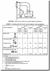
The significant forces produced are sinusoidal at first order (compressor shaft speed) or second order (twice shaft speed). Higher order forces are usually negligible for foundation design. Both direct forces and couples are in general present. Table Igives the out-of-balance forces for a variety of cylinder configurations.
The tendency today is to replace the traditional massive concrete foundations with flexible mountings. The natural frequency of the compressor mass when supported on its flexible mounting should be well below the forcing frequency at first or second order, whichever is appropriate. One main advantage of flexible mounting is the degree of isolation of vibration and noise that it provides.
Where a tuned delivery pipe is specified, its dimensions are supplied by the compressor manufacturer and must be strictly adhered to. If this is not practicable, then a pulsation damper must be installed with the shortest possible delivery pipe between the damper and the aftercooler.
Ideally, delivery pipes for medium-sized compressors and large stationary compressors should be welded and provided with flanged connections for fittings. With small compressors, threaded pipe connections are more commonly used.
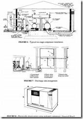
A complete compressor installation involves compressor and drive motor, aftercooler, moisture separator and receiver. The last needs to be located in a cool area and is frequently positioned outside the compressor house as is shown in Figures 4 and 5. However an overriding consideration is that the discharge pipe between compressor and receiver should be kept as short as possible. Where an isolating valve is fitted in the delivery pipework, the line on the compressor side should be protected by a safety valve of sufficient capacity to pass the whole of the compressor delivery without the pressure rising more than I 0% above the set blow-off pressure.
Two further installations, typical of good practice are shown in Figures 6 and 7. See also
the chapters on Compressed Air Filtration and Compressor Controls.
There is an increasing trend for compressors to be made available as an integrated package, which incorporates the control system, heat reclamation, drying and filtration systems to meet the customer’s requirements. They can be craned into a location, with only a power supply and pipe work required. These packaged units are necessarily limited in capacity although that too is increasing. For reciprocating and screw units, capacities up to 1000 1/s are available; dynamic compressors extend the range to about 1700 1/s. The packaged units are very efficient and are replacing many of the older central compressor stations. They are more flexible in application and their reliability means that there is little risk of an unscheduled breakdown disrupting the work of the factory. They can be robust
enough and weather protected so can be located outside. One example of a packaged rotary screw is shown in Figure 8; I x w x h = 2.77m x I .32m x l.7m; the capacity is up to 450 1/s at 7.5 bar or 383 1/s at I 0 bar; the weight is 2600 kg.
Incoming search terms:
- Natural Gas Stationary Compressor Systems mail
- Pump and compressor Station Gas separation Plants mail


