■ OTTO CYCLE: THE IDEAL CYCLE FOR SPARK-IGNITION ENGINES
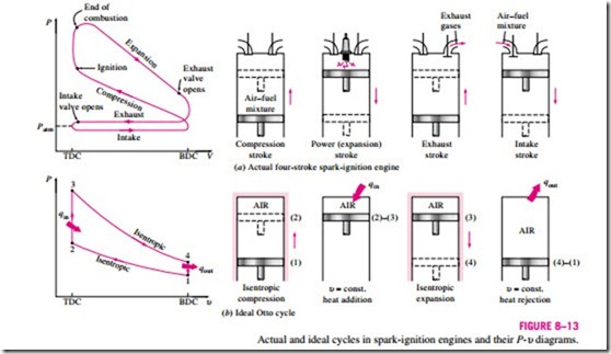
The Otto cycle is the ideal cycle for spark-ignition reciprocating engines. It is named after Nikolaus A. Otto, who built a successful four-stroke engine in 1876 in Germany using the cycle proposed by Frenchman Beau de Rochas in 1862. In most spark-ignition engines, the piston executes four complete strokes (two mechanical cycles) within the cylinder, and the crankshaft completes two revolutions for each thermodynamic cycle. These engines are called four-stroke internal combustion engines. A schematic of each stroke as well as a P–υ diagram for an actual four-stroke spark-ignition engine is given in Fig. 8–13 a.
Initially, both the intake and the exhaust valves are closed, and the piston is at its lowest position (BDC). During the compression stroke, the piston moves upward, compressing the air–fuel mixture. Shortly before the piston reaches its highest position (TDC), the spark plug fires and the mixture ignites, in- creasing the pressure and temperature of the system. The high-pressure gases force the piston down, which in turn forces the crankshaft to rotate, producing a useful work output during the expansion or power stroke. At the end of this stroke, the piston is at its lowest position (the completion of the first mechanical cycle), and the cylinder is filled with combustion products. Now the piston moves upward one more time, purging the exhaust gases through the exhaust valve (the exhaust stroke), and down a second time, drawing in fresh air–fuel mixture through the intake valve (the intake stroke). Notice that the pressure in the cylinder is slightly above the atmospheric value during the exhaust stroke and slightly below during the intake stroke.
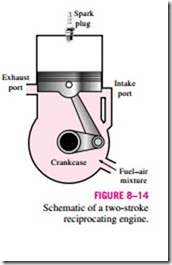
In two-stroke engines, all four functions just described are executed in just two strokes: the power stroke and the compression stroke. In these engines, the crankcase is sealed, and the outward motion of the piston is used to slightly pressurize the air–fuel mixture in the crankcase, as shown in
Fig. 8–14. Also, the intake and exhaust valves are replaced by openings in the lower portion of the cylinder wall. During the latter part of the power stroke, the piston uncovers first the exhaust port, allowing the exhaust gases to be partially expelled, and then the intake port, allowing the fresh air–fuel mixture to rush in and drive most of the remaining exhaust gases out of the cylinder. This mixture is then compressed as the piston moves upward during the compression stroke and is subsequently ignited by a spark plug.
The two-stroke engines are generally less efficient than their four-stroke counterparts because of the incomplete expulsion of the exhaust gases and the partial expulsion of the fresh air–fuel mixture with the exhaust gases. However, they are relatively simple and inexpensive, and they have high power-to-weight and power-to-volume ratios, which make them suitable for applications requiring small size and weight such as for motorcycles, chain saws, and lawn mowers.
Advances in several technologies—such as direct fuel injection, stratified charge combustion, and electronic controls—brought about a renewed interest in two-stroke engines that can offer high performance and fuel economy while satisfying the stringent emission requirements. For a given weight and dis- placement, a well-designed two-stroke engine can provide significantly more power than its four-stroke counterpart because two-stroke engines produce power on every engine revolution instead of every other one. In the new two- stroke engines under development, the highly atomized fuel spray that is injected into the combustion chamber toward the end of the compression stroke
burns much more completely. The fuel is sprayed after the exhaust valve is closed, which prevents unburned fuel from being ejected into the atmosphere. With stratified combustion, the flame that is initiated by igniting a small amount of the rich fuel–air mixture near the spark plug propagates through the combustion chamber filled with a much leaner mixture, and this results in much cleaner combustion. Also, the advances in electronics have made it pos- sible to ensure the optimum operation under varying engine load and speed conditions. Major car companies have research programs underway on two- stroke engines, which are expected to make a comeback in the future.
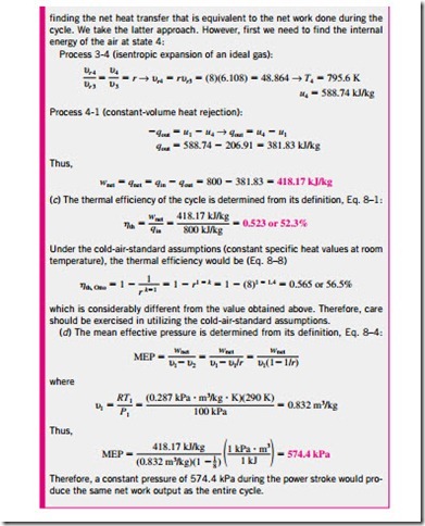
The thermodynamic analysis of the actual four-stroke or two-stroke cycles just described is not a simple task. However, the analysis can be simplified significantly if the air-standard assumptions are utilized. The resulting cycle, which closely resembles the actual operating conditions, is the ideal Otto cycle. It consists of four internally reversible processes:
1-2 Isentropic compression
2-3 Constant-volume heat addition
3-4 Isentropic expansion
4-1 Constant-volume heat rejection
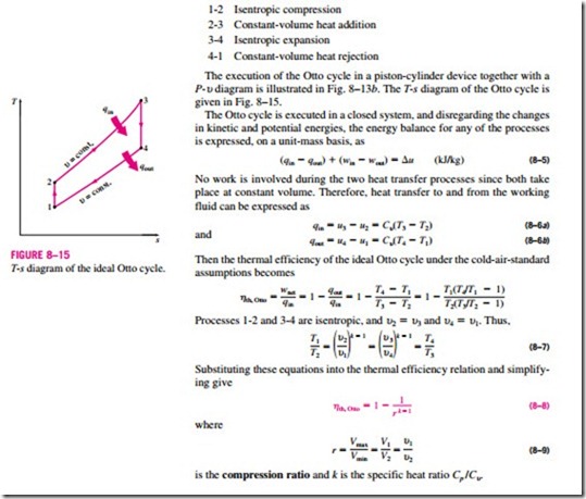
The execution of the Otto cycle in a piston-cylinder device together with a P–υ diagram is illustrated in Fig. 8–13b. The T–s diagram of the Otto cycle is given in Fig. 8–15.
The Otto cycle is executed in a closed system, and disregarding the changes in kinetic and potential energies, the energy balance for any of the processes is expressed, on a unit-mass basis, as
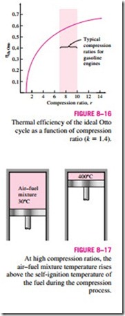
Equation 8–8 shows that under the cold-air-standard assumptions, the thermal efficiency of an ideal Otto cycle depends on the compression ratio of the engine and the specific heat ratio of the working fluid (if different from air). The thermal efficiency of the ideal Otto cycle increases with both the compression ratio and the specific heat ratio. This is also true for actual spark- ignition internal combustion engines. A plot of thermal efficiency versus the compression ratio is given in Fig. 8–16 for k = 1.4, which is the specific heat ratio value of air at room temperature. For a given compression ratio, the thermal efficiency of an actual spark-ignition engine will be less than that of an ideal Otto cycle because of the irreversibilities, such as friction, and other factors such as incomplete combustion.
We can observe from Fig. 8–16 that the thermal efficiency curve is rather steep at low compression ratios but flattens out starting with a compression ra- tio value of about 8. Therefore, the increase in thermal efficiency with the compression ratio is not that as pronounced at high compression ratios. Also, when high compression ratios are used, the temperature of the air–fuel mixture rises above the autoignition temperature of the fuel (the temperature at which the fuel ignites without the help of a spark) during the combustion process, causing an early and rapid burn of the fuel at some point or points ahead of the flame front, followed by almost instantaneous inflammation of the end gas (Fig. 8–17). This premature ignition of the fuel, called autoignition, produces an audible noise, which is called engine knock. Autoignition in spark-ignition engines cannot be tolerated because it hurts performance and can cause engine damage. The requirement that autoignition not be allowed places an upper limit on the compression ratios that can be used in spark-ignition internal combustion engines.
Improvement of the thermal efficiency of gasoline engines by utilizing higher compression ratios (up to about 12) without facing the autoignition problem has been made possible by using gasoline blends that have good an- tiknock characteristics, such as gasoline mixed with tetraethyl lead. Tetraethyl lead has been added to gasoline since the 1920s because it is an inexpensive method of raising the octane rating, which is a measure of the engine knock resistance of a fuel. Leaded gasoline, however, has a very undesirable side ef- fect: it forms compounds during the combustion process that are hazardous to health and pollute the environment. In an effort to combat air pollution, the government adopted a policy in the mid-1970s that resulted in the eventual phaseout of leaded gasoline. Unable to use lead, the refiners developed other techniques to improve the antiknock characteristics of gasoline. Most cars made since 1975 have been designed to use unleaded gasoline, and the compression ratios had to be lowered to avoid engine knock. The thermal efficiency of car engines has decreased somewhat as a result of decreased compression ratios. However, owing to the improvements in other areas (reduction in overall automobile weight, improved aerodynamic design, etc.), to- day’s cars have better fuel economy and consequently get more miles per gallon of fuel. This is an example of how engineering decisions involve com- promises, and efficiency is only one of the considerations in final design.
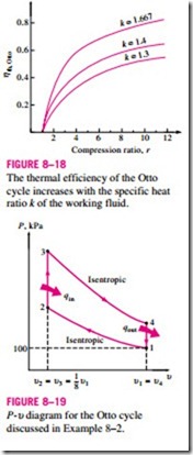
The second parameter affecting the thermal efficiency of an ideal Otto cycle is the specific heat ratio k. For a given compression ratio, an ideal Otto cycle using a monatomic gas (such as argon or helium, k = 1.667) as the working fluid will have the highest thermal efficiency. The specific heat ratio k, and thus the thermal efficiency of the ideal Otto cycle, decreases as the molecules of the
working fluid get larger (Fig. 8–18). At room temperature it is 1.4 for air, 1.3 for carbon dioxide, and 1.2 for ethane. The working fluid in actual engines contains larger molecules such as carbon dioxide, and the specific heat ratio de- creases with temperature, which is one of the reasons that the actual cycles have lower thermal efficiencies than the ideal Otto cycle. The thermal efficiencies of actual spark-ignition engines range from about 25 to 30 percent.
Incoming search terms:
- ideal cycle for spark ignition
- ideal cycle for spark ignition engine
- https://yandex ru/clck/jsredir?from=yandex ru;search;web;;&text=&etext=1822 3muPOqdp31vQTNeTUWON4oiAm93jgj9GGAP__egb56NEUO4d6owGc0MeGB5qLSFYHN2x3C6DdVu2KABsB4vELA 2df623ba185df61108da2eacb15db26b9a9d97a0&uuid=&state=_BLhILn4SxNIvvL0W45KSic
- ideal cycle for si engine
- ideal cycle for spark ignition engines
- spark ignition cycle
