Meter-out operation
In the meter-out operation shown in Figure 6.39, the direction of the flow through the circuit is simply changed as can be made out from the diagram. It is the opposite of a meter-in operation as this change in direction will cause the fluid leaving the actuator to be metered. The advantage with the meter-out operation is that unlike in the case of meter-in operation, the cylinder here is prevented from overrunning and consequent cavitating.
Figure 6.39
Meter-out operation
One major problem confronting the meter-out operation is the intensification of pressure in the circuit which can in tum occur on account of a substantial differential area ratio between the piston and the rods. Pressure intensification occurs on the rod side when the meter-out operation is carried out without a load on the rod side of the cylinder and
can result in failure of the rod seals. It is therefore seen that both the meter-in and meter out operations have their relative advantages and disadvantages and only the application determines the type and nature of flow valve placement.
Valve characteristics
The inherent valve flow characteristics describe the relationship between valve travel or rotation and the change in flow coefficient:
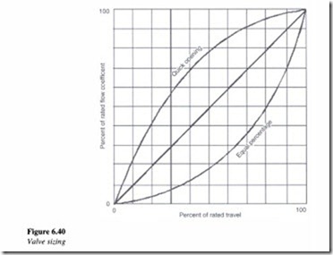
• Linear: The valve characteristic is said to be linear when the change in the flow coefficient is directly proportional to the change in the valve travel.
• Equal percentage: With an equal percentage characteristic, equal increments of valve travel produce equal percentage changes in the existing flow coefficient.
• Quick opening: This characteristic results in a rapid increase in the flow coefficient, with the valve reaching almost maximum capacity in its first 50% of the travel.
• Shape of opening: This characteristic is caused by a change in the shape of the port as valve travel changes.
• Capacity: The larger the opening, the greater is the flow coefficient. Therefore, at maximum valve travel, the equal percent characteristic will have the lowest flow coefficient.
The graph below contains a graphical representation of the above characteristics (Figure 6.40).
In selecting a control valve, while factors such as valve material, pressure and temperature ratings are very important, choosing the correct valve size also assumes equal importance. Simply specifying a valve size to match the existing pipeline size is
impractical and can lead to improper functioning of the entire system. Obviously, a valve which is too small will not give the rated flow rate while a valve too large in size would be rather expensive and result in improper control.
Using the principle of conservation of energy, Daniel Bernoulli discovered that as a liquid flows through an orifice, the square of the fluid velocity is directly proportional to the pressure differential across the orifice and inversely proportional to the specific gravity of the fluid. Hence, greater the pressure differential, higher will be the velocity while on the other hand, greater the fluid density, lower will be the velocity. Logically, the fluid flow rate for liquids can be calculated by multiplying the fluid velocity times the flow area.
After taking into account the proportionality relationship, energy losses due to friction, turbulence and varying discharge coefficient for various orifices, the sizing equation can be written as follows:
Where Kv is the flow in m3/h of water at a pressure differential of I atmosphere. It is known as the valve-sizing coefficient and is a function of length, diameter and material friction:
Q is the flow in m 3/h
R is the reduction factor.
This reflects the ratio of pressure drop across the valve (due to flashing and cavitations) and the pressure recovery profile of the system.
qJ is the density in kg/m 3
!}.p is the pressure drop in psi.
For a given flow rate, a high Kv corresponds to a lower !}.p. However, valve sizing is usually carried out on the basis of the following equation,
Where
Q is the flow rate in gpm
Cv is the sizing coefficients for liquids
!}.p is the pressure drop in psi
G is specific gravity.
To size a valve, it is required to calculate the values of Kv and Cv at maximum flow rate conditions using a value of !}.p, which is allowable. Initial valve selection is to be made by using a graph or chart allowing a valve travel of less than 90% at maximum flow and not less than 10% at minimum flow.
Servo valves
Introduction
The hydraulic systems, subsystems and hydraulic components that have been discussed so far have had open-loop control or in other words power transfer without feedback. We shall now take a look at servo or closed loop control coupled with feedback sensing devices, which provide for a very accurate control of position, velocity and acceleration of an actuator.
A servo valve is a direction control valve, which has an infinitely variable positioning capability. Thus, it controls not only the direction of the fluid flow but also the quantity. In a servo valve, the output controlled parameter is measured with a transducer and fed back to a mixer where the feedback is compared with the command. The difference is expressed in the form of an error signal which is in tum used to induce a change in the system output, until the error is reduced to zero or near zero. A typical example is the use of a thermostat in an automatic furnace whose function is to measure the room temperature and accordingly increase or decrease the heat in order to keep it constant. Let us now discuss in brief, the various components that comprise a servo system.


