Control valves
Types of valves
Pneumatic valves can be divided into three main categories defined by the function they perform: directional control, flow control and pressure control. They can be further divided into those valves which control the airflow to carry out a power function and those which perform a control function. The latter includes a number of specialised valve types which only perform a logic function in control circuits.
They can be also be classified by the method of construction- seated valves, sliding spool valves and variable orifice valves.
Directional control valves
Directional control valves are categorised by the number of port openings or ways; a two port (two-way) valve either opens or closes a flow path in a single line; a three-port (three way) valve either opens or closes alternative flow paths between one or other of two ports or a third port. Other basic configurations are four-port or five-port.
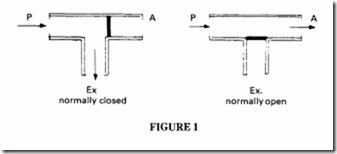
Such valves can also be described by the number of positions provided and also whether the outlet is open or closed in the non-operated position, ie normally open or normally closed respectively. Description may be simplified by giving number of ports and positions as figures separated by a stroke ega 4/2 valve is a four-port, two-position valve. Figure 1, for example, shows a three-way, two-position directional control valve in a simple diagrammatic form.
The three-way two-position valve is thus a logical choice for a single acting cylinder
control circuit control or for any other single circuit where the down stream air has to be exhausted. It is not necessarily a complete answer to such circuits and there are cases where the use of two two-way, two-position valves may be preferred.
Increasing the number of ports, and if necessary the number of positions, extends the switching capability of the valve. The four-way, two-position valve of Figure 2 has two through-connections. In one position Pis connected to A, and B can exhaust downstream air through E. In the second position, Pis connected to B, and A can exhaust downstream through E. A four-way, two-position valve can therefore be used to operate a double acting cylinder or any other device requiring alternate pressure and exhaust in two connecting lines.
While this is a logical control valve choice for a double-acting cylinder there are instances where the use of two three-way two- position valves may be preferred for close coupling or the mounting of valves directly on the cylinder ports.
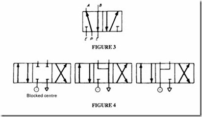
The five-way two-position valve shown in Figure 3 is similar to the four-way valve except for the provision of an extra exhaust port. Thus when either A orB is switched to exhaust, it operates through a separate exhaust port; this can have advantages in particular applications.
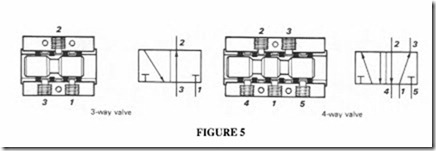
The other directional valve is the four-way, three-position valve which can have three possible modes (Figure 4). In the first (left) the function is similar to a four-way two position valve except that an additional position is available with all ports blocked, ie no
flow is possible through the valve in either direction; this is the normal position. A typical application is the control of a double acting cylinder in which a hold facility is available where air can be trapped on both sides of the piston.
In the second (centre), conventional four-way switching is available from the two extreme positions, but the mid position shuts off the supply and connects both downstream lines to exhaust through the valve. This type is used either with double acting cylinders where it is required to free the piston by exhausting air from both sides of the cylinder, or with motors which are required to free wheel in the off position.
In the third mode (right), normal switching is available from the two extreme positions, but the centre position provides pressurised air to both downstream lines, with the exhaust closed. This provides an alternative hold facility for double acting cylinders with both sides of the cylinder continuously pressurised. This will not give true hold on a single-rod cylinder unless the pressure is dropped in the line to the blank side of the piston to compensate for the loss of effective piston area on the rod side.
Spool valves
Spool valves are the usual choice for directional control, because they can be manufactured to give complicated connections in a simple sliding mechanism. They are straight forward to manufacture, although for good sealing a fine surface is required on both the spool and the barrel with close tolerances to ensure minimum clearances. Glandless spool valves normally require match grinding or a lapped fit between spool and body. Spools may be either stainless steel or aluminium; stainless for the glandless type and aluminium for the sealed type.
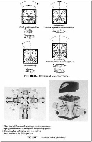
Spool valves have two elements: a cylindrical barrel in which slides a plunger. Port blocking is provided by lands or full diameter sections on the spool, separated by waisted sections which provide port interconnections through the barrel. This provides multi-way and multi-position switching. Spool valves have another advantage: the forces on them are balanced when in one of their selected positions; the forces are not necessarily in balance when in movement from one position to another Spool valves with seals are of simple construction and design. Seals, which may be 0-rings or square section, are positioned between the valve spaces, so that there is a seal between each port and on the outside of the two outer ports (see Figure 5).
The seals may be located in the valve barrel, in which case they are inserted into grooves
machined in the inner surface, or in plastic or metal cages mounted on the inner face of the barrel. Alternatively the seals may be inserted in grooves in the spool. The disadvantage of valves with elastomer seals is that they have to move over the port openings in the case of seals on the spool or by the edge of the spool in the case of seals in the barrel. In either case they may be subject to cutting action or distortion. Some valves have ports drilled with a number of fine holes designed to overcome the possibility of seal cutting.
0-rings are manufactured to wide tolerances which can cause problems: either the seal is loose, which allows leakage, or is tight which increases the static friction (stiction). It is preferable, in valves which are required to have a long operating life, to use square section or other special section seals; these are often backed by PTFE rings.
Elastomer bonded spools have also been developed to overcome the difficulties of using 0-rings. These comprise a metal core to which a thin coating of elastomer is vulcanised. The coating is chemically hardened and ground to a fine tolerance, providing a seal material with good elasticity and compression properties. They are claimed to have a life of20 million cycles compared with more than 1OOmillion cycles for a match ground spool.
Rotary valves
Rotary valves have the advantage that they are adaptable to multi-outlet working. There are two types of rotary valve. One is a form of selector valve with the moving element rotating over a fixed plate to open or block ports drilled in the plate. Channels cut in the rotary plate can provide transverse flow. Sliding plate valves are restricted to two-, three or four-way operation, see Figure 6.
An example of a versatile form of rotary valve is shown in Figure 7. This consists of a square or hexagonal body with four or six peripheral ports, communicating with a central chamber. An operating spindle passes through this chamber, operating spring-loaded poppets in individual ports by cam action. By choosing different combinations of spindle and port spools a variety of different switching combinations are possible. A number of valves of this type may be ganged together to form a multi-bank valve.
Seated valves
These can be either poppet, ball or disc valves with metal to metal seats or metal to elastomer seats. The latter are preferred for pneumatic use where good sealing is preferred for conserving air.
Poppet valves require a minimum movement to achieve full opening; they have a low flow resistance when open and give a good seal when closed. They require a large operating force because of the inherent pressure unbalance on the poppet, which in practice limits their use to solenoid or pilot operation.
A simple poppet valve designed for a pressure of I 0 bar may require an operative force as large as 100N because of its unbalance. Full opening is achieved with only a small travel giving a rapid flow response to a signal, which can be of advantage in high speed applications in pilot circuits.
A limitation of a poppet valve is its restricted switching ability. The basic poppet is capable of only an on-off switching function, so a combination of poppets is needed to perform a three- or four-way function; spool valves are normally used for such duties.
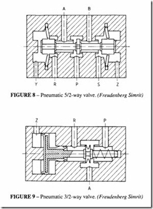
Figure 8 shows a pilot operated 5/2 poppet valve. The diaphragms at the two ends are crucial for operation of this valve . Pilot pressure in ports Y or Z causes the triggering of the valve, which admits air from P to either A or B. For solenoid operation of this valve, either a solenoid replaces the pilot (if the operating force is small) or the pilot pressure itself can be controlled by a solenoid . An alternative method of operation is shown in Figure 9 where pilot pressure selects triggering in one direction, and a spring return in the other.
Ball valves
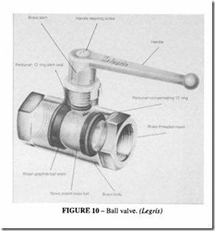
These are used as shut-off valves or to direct flow to, or isolate flow from , a circuit. The construction consists of a spherical ball , located by two resilient sealing rings backed by 0-rings, with a hole through one axis which connects inlet to outlet (Figure I 0). Full bore flow is possible when the hole is aligned with one axis of the valve. A quarter turn is sufficient to close the valve. A three-way version is also available to port the flow to one of two lines; this requires a half turn . Bore sizes are available up to 50 mm. With low friction seals, the torque required to operate them is small: a 50 mm valve of the design shown in Figure 10, for example, requires only 12 Nm. The self-compensating design ensures leak free operation with a long life.
For pneumatic circuits it is often desirable to make sure that when the supply is cut off by means of such a valve, the downstream leg is vented. A venting ball valve has a venting passage machined into the ball which does this.
Standard valve symbols
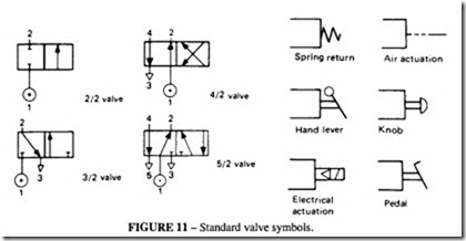
Symbols used for designating valves on pneumatic circuits are conventionally used in the form of adjacent squares, each square representing one position of the valve, and this system is adopted whatever the detailed construction of the valve. A two-position valve would have two adjoining squares, and a three position valve three adjoining squares. Interior connections between points in each position are then indicated by an arrow or arrows within the appropriate square, together with some indication of the unconnected points. Standard valve symbols are shown in Figure II.Additional symbols may also be appended showing the method of operation. A complete set oflnternational Symbols are give in the chapter on Graphical Symbols.
Port 1 is the main supply port, other odd numbers denote exhaust ports and even numbers the outlet ports. Port 3 is always internally connected to port 2 when the valve is in one position. In the reverse position on a five-port valve, port 5 is always connected to port 4.
Although this numbering is standardised, it is not always used and other numbering systems may be used for particular applications.
With increasing automation the majority of valves used in factory installations are sub base mounted, ie with valve bodies in block form for mounting on a common baseplate or manifold; all lines are connected to the base. This arrangement is very flexible in use, because it allows for easy replacement of valves and servicing. For mobile equipment and for heavy duty applications such as offshore, most valves are of in-line configuration, with direct connection of inlet, outlet and exhaust lines.
With sub-base or manifold mounting the valve body has no tapped connections. All internal ports are brought to the base of the valve and connection is completed by mounting on a matching sub-base or manifold, carrying corresponding ports. Joints are sealed with gaskets or 0-rings.
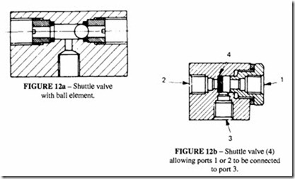
A shuttle valve gives an outlet from either one or two press uri sed inlets (whichever has the greater pressure): the higher pressure inlet moves the shuttle to a position where it blocks the other inlet. It is thus more of a special valve than a true directional control valve and its main use is for logic OR switching.
Non-return valves
These allow the flow of air in one direction only, the other direction through the valve being blocked at all times to the airflow. The valves are usually designed so that the check is pressurised by the downstream pressure and a spring loaded ball or cone.
The simplest type of non-return valve is the check valve, which completely blocks airflow in one direction and allows flow in the opposite direction, with minimum pressure drop across the valve.
As soon as the inlet pressure in the free flow direction overcomes the internal spring force, the check which can be either a ball or poppet is lifted clear of the valve seat. Alternatively the check may be lifted off the valve seat by some means, as in the case of a quick connect coupling.
Check valves are installed where different components need to be isolated, or restriction of flow through a component in one direction only is required for safety considerations.
Quick exhaust valves
An exhaust valve (quick relief valve), as shown in Figure 13, is designed to increase the speed ofmovementofacylinder by allowing the exhaust air to vent directly to atmosphere. Ideally a quick exhaust valve should be screwed directly into the cylinder ports to obtain maximum effect.
Air pressure entering the inlet from a selector valve forces a cup seal against the seat of the exhaust port and flows into the cylinder port. The exhaust air flowing from the cylinder port presses against the lips of the seal, forcing it against the inlet port to close it. The exhaust air then flows from the cylinder directly to atmosphere without having to go through the selector valve.
Flow control
Air flow is controlled by using throttling devices. The geometry can range from that of a fixed orifice to an adjustable needle valve or shaped grooves, capable of supplying progressive throttling. The basic function may be combined with a second function such as non-return in the opposite direction.
Speed control valves
These valves for pneumatic applications are usually restrictorcheck valves. The throttling function is provided by a flow control orifice and the incorporation of a check function also makes them non-return valves when the orifice is closed. Usually the throttle is adjustable to permit regulation of the air flow through the valve, with throttling in one direction of the flow only. In the other direction, free tlow is provided through the check valve.
Figure 14 shows a needle exhaust port tlow regulator. This type of valve is for use with a five port fully balanced spool valve for cylinder speed control. The setting of the needle regulates the rate of tlow of air to exhaust through the control valve, regulating the speed
of movement of the cylinder. A flow regulator is required in each of the normal exhaust ports of a five-port valve to control the speed of the cylinder in both directions.
A secondary effect of exhausting air directly to atmosphere from the valve is that it tends to be noisy. This can be overcome by the fitting of exhaust silencers. Exhaust flow regulators can be supplied as complete regulator/silencer assemblies comprising the regulator and silencer element screwed to the regulator (Figure 15).
The regulator unit can adjust flow from zero to maximum within six or seven turns, depending upon design.
Speed control
The speed of operation of an air cylinder can be controlled by throttling either the inlet or outlet or both. The degree of speed control available from such a simple method is suitable for a wide range of applications, although the actual response time will be variable, because of the varying compressibility of air against different loads.
Actual control of speed, however, is often Jess important than reducing the speed of operation to a satisfactory level. Excessive speed can result in dangerous inertial loading, increase cylinder wear and waste air.
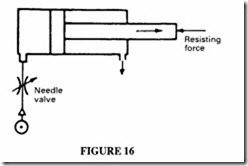
Speed control accomplished by metering the inlet air will only produce a constant speed if the resistive load is constant (Figure 16). Pressure will first build up in the cylinder until the force available overcomes the static friction and the resistive load, when the piston will start to move. It will then continue to move at constant speed, so long as the resistive load is constant, with speed governed by the rate of air admission. Any change in the resistive load will cause a corresponding change in the speed of movement.
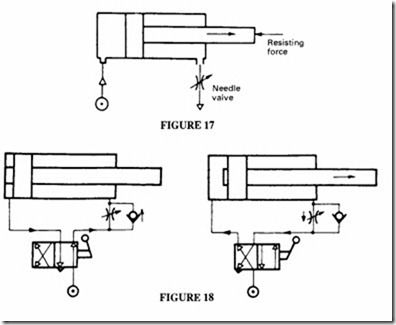
Speed control by metered exhaust (Figure I7) will tend to give an initial rapid movement followed by a slowing down as air is compressed on the exhaust side of the
piston; the movement is likely to be jerky. Much better control is achieved if the modified circuit of Figure 18 is used where the piston is held in the retracted position under pressure.
When the control valve is operated, the piston will start to move forward through pressure applied to the head end before the air has had time to leak away from the rod end. The result is freedom from initial jerk and smooth movement throughout, whilst any tendency to jerk forward, should the resisting force be removed, is minimised.
The general recommendation is that speed control should be applied by throttling the exhaust. A combination of methods may be needed in some circumstances. Often a degree of trial and error is required.
Provided that the load is reasonably constant and unidirectional, good accuracy can be obtained by simple methods. With very low piston velocities, friction may become the most important parameter. To achieve consistent results with speed control it may be necessary to use cylinders with low friction seals and well-finished bores.
Formore precise speed control, and to take care of fluctuations in load and line pressure, surge damping may be applied to the system. This can be done hydraulically with an external dashpot or the use of an oversize system with a surge tank in the circuit. More sophisticated methods may sometimes be required; these include velocity feed back with servo-valves.
Slow start flow control valves
A slow start (or soft start) valve allows pressure to increase gradually after the system has been vented for some reason. It ensures that cylinders or other protected devices return slowly to the end of their stroke after the pressure is restored. Depending on the desired behaviour of the circuit on restoration, a slow start valve may be mounted next to a single direction control valve or further back in the circuit where it controls several cylinders. In the latter case, the cylinders will return to their end-of-stroke position, one after the other
depending on their relative resistance to motion. These valves incorporate a needle valve which regulates the speed of pressurisation. Once the soft start system has opened fully, the system works normally, with no restriction to flow. See Figure 19.
This type of valve may also be used to control pressure decay when the system is shut down.
Time delay valves
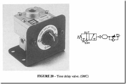
This type of valve puts a time delay into the system. It may be used when it is necessary to ensure that a particular sequence of movements is completed before another sequence is commenced. The second sequence is protected by a time delay valve. It consists of a restrictor valve which charges a reservoir in a controllable way until the pressure in the reservoir has built up to a level where it can trigger a pilot valve (Figure 20); a non-return valve allows the reservoir to be emptied rapidly for the next timing cycle. The time delay depends on two factors: the airflow through the restrictor and the volume of the reservoir. It may be considered to be the pneumatic equivalent of a resistor/capacitor electronic circuit. These valves normally incorporate a small reservoir in the body of the valve and rely only on the size of the restrictor to control the time delay, which in a typical commercial valve is adjustable up to 60 seconds . For longer time delays of several minutes, the size of the reservoir may have to be increased externally.
Incoming search terms:
- wabco five way valve pumping air on rwo ports only
- What is the function of pilot valve used in grinding machine circuit
- function of pilot valve used in grinding machine
- function of pivot valve used in grinding machine
- Fuction of exhaust valve
- Fuction of pilot valve used in grinding machine circuit
- fuction of pneumatic cylinder
