Automatic Venting at End of Cycle
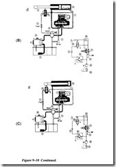
In systems where it is not necessary to hold pressure at the end of a cycle, it is possible to unload the pump by automatically venting the relief valve. Figure 9-10 shows such a system using a cam-operated pilot valve to vent the relief valve.
Midstroke Extending
In view A of Figure 9-10, the machine cycle begins when the solenoid of the spring off set directional valve is energized. Pump output is to the cap end of the cylinder. The vent line from the directional control valve is blocked at the cam-operated pilot valve.
Midstroke Retracting
In view B of Figure 9-10, the limit switch has contracted the cam at the end of the extension stroke. This contact breaks the circuit of the solenoid. The directional
control valve has shifted to retract the cylinder. The relief valve vent connection is still blocked.
Automatic Stop
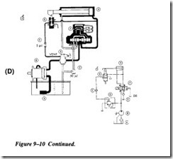
View C of Figure 9-10 illustrates the circuit at the end of the retraction stroke. The cam on the cylinder opens the venting pilot valve. The relief valve vent port is thus connected to the line from the cap end of the cylinder and the valve is vented through the inline check
valve, the directional control valve, and the right-angle check valve. Pilot pressure for the directional valve is maintained at a value determined by the spring loads in the balanced piston of the relief valve, the vent line check valve, and the tank line check valve.
Push-Button Start
When the start button (view D) is depressed, it energizes the solenoid, and the direc tional valve shifts to direct pump output into the cap end of the cylinder. This causes the check valve in the vent line to close and prevent the relief valve from venting. Pressure again builds up and the cycle is repeated.
