Fault-finding
Fault-finding is often performed in a random and haphazard manner, leading to items being changed for no systematic reason beyond ‘Fred got it working this way last time’. Such an approach may work eventually (when every component has been changed!) but it is hardly the quickest, or cheapest, way of getting a faulty system back into production. In many cases more harm than good results, both with introduction of dirt into the system, and from ill advised ‘here’s a control adjustment; let’s twiddle it and see if that makes any difference’ approach. There must be a better way.
There are three maintenance levels. First line maintenance is con cerned with getting faulty plant running again. When the cause of a fault is found, first line staff have the choice of effecting a first line, on site, repair (by replacing a failed seal, say) or changing the com plete faulty unit for a spare. This decision is based on cost, time, availability of spares, technical ability of staff, the environment on site and company policy.
Second line maintenance is concerned with repair to complete units changed by first line maintenance staff. It should be per formed in clean and well-equipped workshops. Work is usually well-defined and is often a case of following manufacturers’ manuals.
The final level is simply the return of equipment for repair by manufacturer. The level at which this is needed is determined by the complexity of equipment, ability of one’s staff, cost and the turn round time offered by the manufacturer.
Of these three levels; first line maintenance is hardest as work is ill-defined, pressures from production staff are great and the respon sibility high. Unfortunately, it is too often seen as a necessary evil.
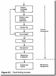
Fault-finding is, somewhat simplistically, represented by Figure 8.5. All the evidence on the fault gathered so far is evaluated, and possible causes considered. The simplest test to reduce the number of possibilities is then performed and the cycle repeated until the fault is found.
The final steps in Figure 8.5 are concerned with fault recording and fault analysis. Any shift crew (which performs almost all the first line repairs) only sees one quarter of all faults. The fault recording and analysis process shows if there is any recurring pattern in faults, indicating a design or application problem. Used diplomatically, the records may also indicate shortcomings in crews’ knowledge and a need for training.
Modern plants tend to be both complex and reliable. This means that a maintenance crew often sees a plant in detail for the first time when the first fault occurs. (Ideally, of course, crews should be involved at installation and commissioning stages – but that is another story!). It is impossible to retain the layout of all bar the
simplest of systems in the mind, so it is essential to have schematic diagrams readily available.
Equally important, readings at each test point should be documented when the system is working correctly. It is not much use to know pressure at TP3 is 15 bar, the motor draws 75 A or flow to rotary actuator C is 1500 1 min-1 under fault conditions, without knowing what the normal readings are.
It can often be difficult to decide what a fault really is; usually the only information is simply ‘the Firkling Machine is not working’. The first diagnostic step is, therefore, to establish what is really wrong- whether there is one fault or several from a common cause. A quick visual and manual check should be made for any obvious aberrations; noise, vibration, heat, leaks, unusual motor current.
From maintenance records it should be possible to see if any recent work has been done or if this is a recurring fault. Recent work is always suspect- particularly if the unit has not been used since the work was done. Some points to check if work has recently been performed are:
• whether the correct units were fitted. Stores departments are not infallible and lookalike units may have been fitted in error. Non return valves can sometimes be fitted the wrong way round;
• whether all handvalves are correctly open or shut. Many systems are built with standby pumps or compressors with manual change over. These are (in the author’s experience) a constant source of trouble after a changeover (one invariable characteristic seems to be one less valve handle than there are valves!). Valves can also creep open. Figure 8.6 shows a common fault situation with two hydraulic units, one in use and one standby. If any of the hand isolation valves V 1 to V4 are set incorrectly open on the main or standby units, flow from the duty unit returns direct to tank via the centre position of the standby directional valve and the actu ator will not move;
• after electrical work, check the direction of rotation of the pump or compressor. Most only operate in one direction, usually defined with an arrow on the casing, and may even be damaged by prolonged reverse running;
• have any adjustments been ‘twiddled’ or not set correctly after an item has been changed? On many directional valves, for example, the speeds of operation from pilot to main spool can be set by Allen key adjustments. If these are maladjusted, the main spool may not move at all.
If no recent work has been done, and these quick checks do not locate a fault, it is time to start the fault-finding routine of Figure 8.5. One advantage of pneumatic systems is their natural break into distinct portions: (1) a supply portion up to and including the receiver and (2) one or more application portions after the receiver.
The pressure gauge on the receiver allows a natural fault-finding split.
Problems generally fall into three types; a lack of force, low speed (or no speed), or erratic operation. Lack of force or no move ment is generally a pressure-related fault. Low speed arises from a flow fault. Erratic operation can arise from sticking valves or from air in a hydraulic system.
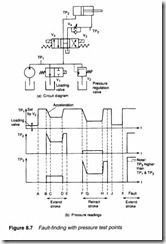
Usually pressure monitoring is much easier than flow monitoring but is often misunderstood. A typical example of fault-finding using pressure test points is given in Figure 8.7. Up to time A the system unloads via the solenoid-operated unloading valve V 1. When valve V 1 energises, pressure rises to the setting of the relief valve V2. At time C, directional valve V3 calls for the cylinder to extend.
Pressure falls as the cylinder accelerates, until the cylinder is moving at constant speed when P=F/A. At time D, the cylinder reaches the end of travel, and the pressure rises back to the setting of the relief valve. Directional valve V3 de-energises at E. Note the low pressures in return line test points.
A similar retract stroke takes place during time F to I. The pres sure between G and H is lower than between C and D, because fric-
tion alone opposes the movement. The loading valve comes off at time J.
It is important to monitor return line pressure. A fault exists from time X onwards; the return line from the cylinder is blocked, possibly because the spool in the meter-out flow control valve has jammed, allowing no fluid to return. At time Y the directional valve operates causing a rise in pressure on test point TP2 to the setting of the relief valve. Because of the blockage in the return line, point TP3 also rises to a higher pressure because of the lower annulus area on the return side of the piston (P1A=P2a, remember!).
Pressure is therefore a good indication of what is going on in a system, the pressure being the lowest demanded by the loading/ unloading valves, the relief valve(s) or the load itself.
A hydraulic pump is a positive displacement device (see Chapter 2). This has useful implications when fault-finding. If a pump is working its flow must be getting back to tank via some route. If it does not the pressure will rise and the oil will eventually go every where! Tracking the oil flow route by as simple a method as fol lowing warm pipes by hand can sometimes indicate what is wrong.
Remember these basic facts for fault finding:
• Knowing if the pump is delivering fluid is vital. If there is not a UCC system 22 or similar flow sensor immediately after the pump but before the first relief valve consider installing one as soon as possible
• Hydraulic pumps are invariably positive displacement pumps. If a pump is delivering fluid it must be going somewhere.
• Acceleration is determined by pressure
• Force is determined by pressure
• Velocity (speed) is determined by flow
• The pressure at any point is determined by the lowest pressure the system can provide under the current conditions.
The interface with the electrical control can cause confusion. The control sequence should be clearly understood. Figure 8.8 shows a typical electrical/hydraulic scheme used to build a tight pack of objects. An object is placed onto the skid, and its presence noted by a proximity detector connected as an input to a programmable controller (PLC).
When the PLC sees an object, it energises the loading valve, and causes the cylinder to extend. The cylinder extends until the front limit switch LS 1 makes (for the first few objects) or the pressure switch PS2 makes (indicating a full stalled pack) or timeout (indi cating some form of fault). The cylinder then returns to the back limit LS2 or a timeout (again indicating a fault) when the loading valve is de-energised. The PLC also monitors pump action via pressure switch PSI’ which is made whenever the loading valve is energised.
A knowledge of the complete system, both electrical and hydraulic, is required to fault-find on this application. Fault-finding involves checking the sequence by monitoring the state of electrical outputs to solenoids and inputs from limit switches.
All solenoid valves should have an indicator in the plug tops to allow electrical signals to be observed local to the valves. Indicator blocks which fit between plug and valve are available for retro fitting onto systems without this useful feature. It should be remem bered, though, that indications purely show electrical voltage is present – it does not, for example, identify an open circuit solenoid
coil.
Solenoids can operate on AC (usually 110 V AC) or DC (usually 24 V DC). DC solenoids have totally different operating character istics. An AC solenoid has a very high inrush current producing a high initial force on the pilot spool. As the spool moves in, the inductance of the coil rises and current falls to a low holding current (and a low force on the pilot spool). If the pilot spool jams the current remains high, causing the protection fuse or breaker to open or the solenoid coil to bum out if the protection is inadequate. Operation of a 110 volt solenoid system with cold oil is best under taken with a pocketful of fuses.
The current in a DC solenoid is determined by the coil resistance and does not change with pilot spool position. The solenoid does not, therefore, give the same ‘punch’ to a stiff spool but will not bum out if the spool jams. Current in a DC solenoid also tends to be higher requiring larger size cables, particularly if a common return line is used from a block of solenoids.
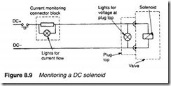
A useful monitoring device is the through-connector with an integral current indicator shown in Figure 8.9. This does give indication of an open circuit coil and combined with the indicator on the plug top can help find most electrical faults.
On most electrically-operated valves the pilot spool can be operated manually by pushing the spool directly with a rod (welding rod is ideal!). Electrical signals should, however, be disabled when operating valves manually, as pushing in the opposite direction to the solenoid can cause the coil to bum out.
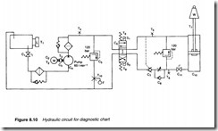
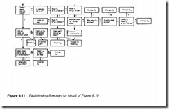
Designers of a system can simplify maintenance by building in a fault-finding methodology from the start. This often takes the form of a flowchart. Figure 8.10 shows a typical system, which can be diagnosed by following the flowchart of Figure 8.11. Such charts cannot solve every problem, but can assist with the majority of common faults. If transducers can be fitted to allow the system to be monitored by a computer or programmable controller, Figure 8.11 could form the basis of a computer-based expert system.
