Conveying capability
Introduction
In Chapter 11 a limited number of materials were considered in order to illustrate the global differences between dilute phase and dense phase conveying. For dense phase conveying only powdered materials having good air retention properties were considered. Within this framework the influence of air flow rate and conveying air velocity were considered, particularly in terms of power requirements and energy considerations.
Conveying with high pressure air was employed in most cases to show the influence on the conveying capability of the different materials being considered. Low pressure conveying data is therefore automatically included in all of the conveying characteristics presented in Chapter 11, but it does tend to get lost and overlooked in the overall scale. Similarly the low pressure, and hence dilute phase conveying, of the materials having good air retention, also tends to disappear into the bottom right hand corner of the overall conveying characteristics of these materials when conveyed with high pressure air.
In this chapter a much wider range of materials is considered and low pressure conveying data is specifically included so that the performance of all types of material can be examined at low values of solids loading ratio. Both sliding bed and plug flow modes of dense phase conveying are considered in the range of materials included.
The influence of materials
The conveying characteristics for different materials can vary significantly. This is particularly so for materials capable of being conveyed in dense phase. At low values of air flow rate the lines of constant conveying line pressure drop can have a wide variety of slopes. There is also the added complexity of different materials having differ- ent minimum conveying limits. Thus for a given air flow rate and conveying line pressure drop, material flow rates for different materials can vary considerably, and the air flow rate necessary to convey different materials can also vary considerably.
Some of these differences were illustrated in the previous chapter with the materials used to show how conveying characteristics are determined and to compare power and energy requirements. These differences, however, are not just a feature of conveying with high pressure air but will be found in low pressure systems also.
Low pressure conveying – Part I
If only low pressure air is available for conveying a material through a pipeline, such as that from a positive displacement blower or a vacuum system, and below about 1 bar gauge, a material will only be conveyed in dilute phase through a pipeline, unless the conveying distance is very short. Conveying data for four different materials are presented in Figure 12.1.
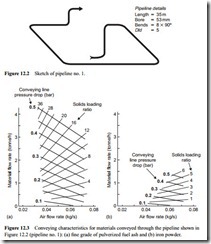
Each material was conveyed up to a limit of 0.5 bar in terms of conveying line pres- sure drop. All four materials were conveyed through the same pipeline, a sketch of which is given in Figure 12.2. A low pressure bottom discharge blow tank was used to
feed each material into the pipeline. Although each material was conveyed in dilute phase, it will be seen that there are significant differences in their conveying capability.
The conveying characteristics for two further materials also conveyed through pipeline no 1 are presented in Figure 12.3.
The differences between the six materials presented are mainly in terms of the mater- ial flow rates achieved, varying from 4.3 tonne/h for the fly ash to 1.4 tonne/h for the iron powder, for a pressure drop of 0.5 bar. Since all the materials were conveyed in dilute phase, and they were all either powders or granular materials, such marked dif- ferences would not be expected in terms of minimum conveying air velocities. With a 0.2 bar pressure drop, these varied between 12 m/s for fly ash and 16 m/s for the coal.
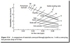
Many different materials have been tested in the pipeline shown in Figure 12.2. To show how the conveying characteristics of different materials can vary in such a low pressure system, the 0.5 bar constant conveying line pressure drop curves from a number of such materials are compared in Figure 12.4.
Different conveying capabilities and air requirements mean that particular care must be taken if an existing system is to be used to convey another material, or if one system is required to convey a number of different materials. If the capability of a sys- tem is dictated by the pressure rating of the air mover, then different material flow rates must be expected, and the feeding device must be capable of meeting the needs of any other material. A different air flow rate may also be required, as shown by the different minimum values for the fly ash and coal in Figure 12.4.
Coal
The coal presented in Figure 12.1a is referred to as ‘pearls’. It has a mean particle size of approximately 10 mm, with a top size of about 20 mm. There were no operating problems in conveying this material through the 53 mm bore pipeline, despite the rela- tively large particle size, although degradation of the coal was a problem [1]. Despite the large particle size, higher material flow rates were achieved than for some of the fine granular materials tested in this pipeline. As the coal had a very wide particle size distribution, and is very friable, there is no possibility of the material being conveyed in anything other than dilute phase in a conventional conveying system. The bulk dens- ity of the coal was about 690 kg/m3 and the particle density 1320 kg/m3.
Sodium chloride (salt)
The common salt conveyed very well, with a conveying performance similar to that of the coal. The mean particle size of the salt was about 390 f.Lm. Like the coal, this material
has no dense phase conveying capability and would not be conveyed in dense phase even if a very much higher air supply pressure was available. The bulk density of the salt was about 1220 kg/m3 and the particle density 2630 kg/m3.
Sodium carbonate (heavy soda ash)
Soda ash has something of a reputation of being a difficult material to convey. Further data on soda ash, albeit light soda ash, is presented in the next chapter. The fact that the material flow rate achieved was rather low may be part of the problem, and part of the reason for showing the performance characteristics of a wide range of materials is to illustrate the fact that a wide range of performance capabilities must be expected, even in dilute phase flow. There is no obvious correlation between any of the material properties and their performance ‘ranking’ in Figure 12.4. The mean particle size of the heavy soda ash tested was about 340 f.Lm. This is yet another material with no natural dense phase conveying capability. The bulk density of the soda ash was about 1160 kg/m3 and the particle density 2500 kg/m3.
Pearlite
Pearlite is an exfoliated type material and had the lowest density of all the materials tested. The bulk density was about 100 kg/m3 and the particle density 800 kg/m3. The mean particle size was about 200 f.Lm. With this combination of properties the mater- ial is capable of being conveyed in dense phase in a conventional conveying system and further conveying characteristics for this material will be found in the next section of this chapter on high pressure conveying.
Pulverized fuel ash (fly ash)
This material had the best performance of all those tested. The mean particle size was about 25 f.Lm. Fly ash generally comes from the combustion of pulverized coal in the boiler of a thermal power plant and consists essentially of the non-combustible constituents in the coal. As a result of the high temperature and relatively low velocity suspension flow during combustion the particle shape is generally spherical. The material, therefore, has very good air retention properties and will readily convey in dense phase. Due to the very high material flow rates achieved, high values of solids loading ratio resulted, and as a consequence the fly ash was on the verge of being conveyed in dense phase with a pressure drop of only 0.5 bar. This explains why the minimum value of air flow rate required reduced with increase in pressure. The bulk density of the fly ash was about 700 kg/m3 and the particle density 1700 kg/m3.
Iron powder
The iron powder conveyed very well and no operating problems were experienced at all. The bulk density of this material was about 2380 kg/m3 and the particle density 5710 kg/m3. Whereas a solids loading ratio of 36 was achieved with the fly ash, a maximum of only six was obtained with the iron powder. The conveying characteristics are typical of those for a material conveyed in dilute phase. The conclusion, however,
must not be that the material will only convey in dilute phase on the basis of this data. The mean particle size of the iron powder was about 64 f.Lm and it had very good air retention properties. As a consequence the material will convey in dense phase, and to prove the point further, conveying characteristics for this material will be found in the next section of this chapter on high pressure conveying. Due to the very much lower material flow rate achieved with the iron powder, 0.5 bar is much too low a pressure drop for this length of pipeline to be at the point of transition to dense phase conveying, as was the case with the fly ash.


