■ BRAYTON CYCLE: THE IDEAL CYCLE FOR GAS-TURBINE ENGINES
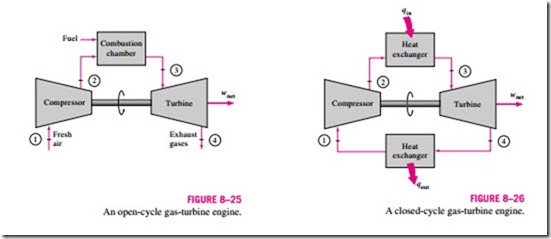
The Brayton cycle was first proposed by George Brayton for use in the reciprocating oil-burning engine that he developed around 1870. Today, it is used for gas turbines only where both the compression and expansion processes take place in rotating machinery. Gas turbines usually operate on an open cycle, as shown in Fig. 8–25. Fresh air at ambient conditions is drawn into the compressor, where its temperature and pressure are raised. The high-pressure air proceeds into the combustion chamber, where the fuel is burned at constant pressure. The resulting high-temperature gases then enter the turbine, where they expand to the atmospheric pressure, thus producing power. The exhaust gases leaving the turbine are thrown out (not recirculated), causing the cycle to be classified as an open cycle.
The open gas-turbine cycle just described can be modeled as a closed cycle, as shown in Fig. 8–26, by utilizing the air-standard assumptions. Here the
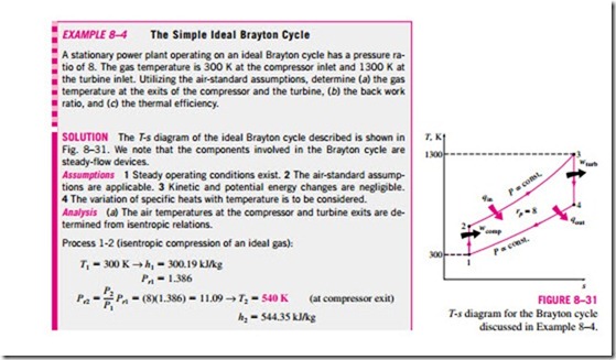
compression and expansion processes remain the same, but the combustion process is replaced by a constant-pressure heat-addition process from an external source, and the exhaust process is replaced by a constant-pressure heat- rejection process to the ambient air. The ideal cycle that the working fluid undergoes in this closed loop is the Brayton cycle, which is made up of four internally reversible processes:
1-2 Isentropic compression (in a compressor)
2-3 Constant-pressure heat addition
Isentropic expansion (in a turbine)
4-1 Constant-pressure heat rejection
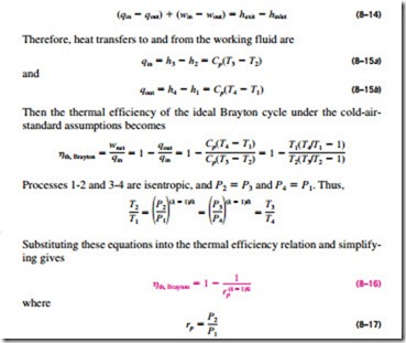
is the pressure ratio and k is the specific heat ratio. Equation 8–16 shows that under the cold-air-standard assumptions, the thermal efficiency of an ideal Brayton cycle depends on the pressure ratio of the gas turbine and the specific heat ratio of the working fluid. The thermal efficiency increases with both of these parameters, which is also the case for actual gas turbines. A plot of thermal efficiency versus the pressure ratio is given in Fig. 8–28 for k = 1.4, which is the specific heat ratio value of air at room temperature.
The highest temperature in the cycle occurs at the end of the combustion process (state 3), and it is limited by the maximum temperature that the turbine blades can withstand. This also limits the pressure ratios that can be used in the cycle. For a fixed turbine inlet temperature T3, the net work output per cycle in- creases with the pressure ratio, reaches a maximum, and then starts to decrease, as shown in Fig. 8–29. Therefore, there should be a compromise between the pressure ratio (thus the thermal efficiency) and the net work output. With less work output per cycle, a larger mass flow rate (thus a larger system) is needed to maintain the same power output which may not be economical. In most common designs, the pressure ratio of gas turbines ranges from about 11 to 16. The air in gas turbines performs two important functions: It supplies the necessary oxidant for the combustion of the fuel, and it serves as a coolant to keep the temperature of various components within safe limits. The second function is accomplished by drawing in more air than is needed for the complete combustion of the fuel. In gas turbines, an air–fuel mass ratio of 50 or above is not uncommon. Therefore, in a cycle analysis, treating the combustion gases as air will not cause any appreciable error. Also, the mass flow rate through the turbine will be greater than that through the compressor, the difference being equal to the mass flow rate of the fuel. Thus, assuming a constant mass flow rate throughout the cycle will yield conservative results for open-loop gas-turbine engines.
The two major application areas of gas-turbine engines are aircraft propulsion and electric power generation. When it is used for aircraft propulsion, the gas turbine produces just enough power to drive the compressor and a small generator to power the auxiliary equipment. The high-velocity exhaust gases are responsible for producing the necessary thrust to propel the aircraft. Gas turbines are also used as stationary power plants to generate electricity as stand- alone units or in conjunction with steam power plants on the high-temperature side. In these plants, the exhaust gases of the gas turbine serve as the heat source for the steam. The gas-turbine cycle can also be executed as a closed cycle for use in nuclear power plants. This time the working fluid is not limited to air, and a gas with more desirable characteristics (such as helium) can be used. The majority of the Western world’s naval fleets already use gas-turbine engines for propulsion and electric power generation. The General Electric LM2500 gas turbines used to power ships have a simple-cycle thermal efficiency of 37 percent. The General Electric WR-21 gas turbines equipped with intercooling and regeneration have a thermal efficiency of 43 percent and produce 21.6 MW (29,040 hp). The regeneration also reduces the exhaust temperature from 600˚C (1100˚F) to 350˚C (650˚F). Air is compressed to 3 atm before it enters the intercooler. Compared to steam-turbine and diesel-propulsion systems, the gas turbine offers greater power for a given size and weight, high reliability, long life, and more convenient operation. The engine start-up time has been reduced from 4 h required for a typical steam-propulsion system to less than 2 min for a gas turbine. Many modern marine propulsion systems use gas turbines together with diesel engines because of the high fuel consumption of simple-cycle gas-turbine engines. In combined diesel and gas-turbine systems, diesel is used to provide for efficient low-power and cruise operation, and gas turbine is used when high speeds are needed.
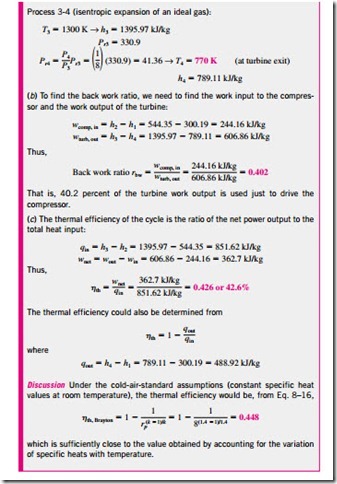
In gas-turbine power plants, the ratio of the compressor work to the turbine work, called the back work ratio, is very high (Fig. 8–30). Usually more than
one-half of the turbine work output is used to drive the compressor. The situation is even worse when the isentropic efficiencies of the compressor and the turbine are low. This is quite in contrast to steam power plants, where the back work ratio is only a few percent. This is not surprising, however, since a liquid is compressed in steam power plants instead of a gas, and the reversible steady-flow work is proportional to the specific volume of the working fluid. A power plant with a high back work ratio requires a larger turbine to pro- vide the additional power requirements of the compressor. Therefore, the turbines used in gas-turbine power plants are larger than those used in steam power plants of the same net power output.
Development of Gas Turbines
The gas turbine has experienced phenomenal progress and growth since its first successful development in the 1930s. The early gas turbines built in the 1940s and even 1950s had simple-cycle efficiencies of about 17 percent be- cause of the low compressor and turbine efficiencies and low turbine inlet temperatures due to metallurgical limitations of those times. Therefore, gas turbines found only limited use despite their versatility and their ability to burn a variety of fuels. The efforts to improve the cycle efficiency was concentrated in three areas:
1. Increasing the turbine inlet (or firing) temperatures This has been the primary approach taken to improve gas-turbine efficiency. The turbine inlet temperatures have increased steadily from about 540˚C (1000˚F) in the 1940s to 1425˚C (2600˚F) today. These increases were made possible by the development of new materials and the innovative cooling techniques for the critical components such as coating the turbine blades with ceramic layers and cooling the blades with the discharge air from the compressor. Maintaining high turbine inlet temperatures with air-cooling technique requires the combustion temperature to be higher to compensate for the cooling effect of the cooling air. However, higher combustion temperatures increase the amount of nitrogen oxides (NOx), which are responsible for the formation of ozone at ground level and smog. Using steam as the coolant allowed an increase in the turbine inlet temperatures by 200˚F without an increase in the combustion temperature. Steam is also a much more effective heat transfer medium than air.
2. Increasing the efficiencies of turbomachinery components The performance of early turbines suffered greatly from the inefficiencies of tur- bines and compressors. However, the advent of computers and advanced tech- niques for computer-aided design made it possible to design these components aerodynamically with minimal losses. The increased efficiencies of the tur- bines and compressors resulted in a significant increase in the cycle efficiency.
3. Adding modifications to the basic cycle The simple-cycle efficiencies of early gas turbines were practically doubled by incorporating intercooling, regeneration (or recuperation), and reheating, discussed in Sections 8–8 and 8–9. These improvements, of course, come at the expense of increased initial and operation costs, and they cannot be justified unless the decrease in fuel costs offsets the increase in other costs. The relatively low fuel prices, the general desire in the industry to minimize installation costs, and the tremendous increase in the simple-cycle efficiency to about 40 percent left little desire for opting for these modifications.
The first gas turbine for an electric utility was installed in 1949 in Oklahoma as part of a combined-cycle power plant. It was built by General Electric and produced 3.5 MW of power. Gas turbines installed until the mid-1970s suffered from low efficiency and poor reliability. In the past, the base-load electric power generation was dominated by large coal and nuclear power plants. However, there has been a historic shift toward natural gas– fired gas turbines because of their higher efficiencies, lower capital costs, shorter installation times, and better emission characteristics, and the abundance of natural gas supplies, and more and more electric utilities are using gas turbines for base-load power production as well as for peaking. The construction costs for gas-turbine power plants are roughly half that of comparable conventional fossil-fuel steam power plants, which were the primary base-load power plants until the early 1980s. More than half of all power plants to be installed in the foreseeable future are forecast to be gas-turbine or combined gas–steam turbine types.
A gas turbine manufactured by General Electric in the early 1990s had a pressure ratio of 13.5 and generated 135.7 MW of net power at a thermal efficiency of 33 percent in simple-cycle operation. A more recent gas turbine manufactured by General Electric uses a turbine inlet temperature of 1425˚C (2600˚F) and produces up to 282 MW while achieving a thermal efficiency of 39.5 percent in the simple-cycle mode. A 1.3-ton small-scale gas turbine la- beled OP-16, built by the Dutch firm Opra Optimal Radial Turbine, can run on gas or liquid fuel and can replace a 16-ton diesel engine. It has a pressure ratio of 6.5 and produces up to 2 MW of power. Its efficiency is 26 percent in the simple-cycle operation, which rises to 37 percent when equipped with a regenerator.
Deviation of Actual Gas-Turbine Cycles from Idealized Ones
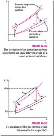
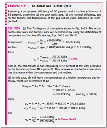
The actual gas-turbine cycle differs from the ideal Brayton cycle on several accounts. For one thing, some pressure drop during the heat-addition and heatrejection processes is inevitable. More importantly, the actual work input to the compressor will be more, and the actual work output from the turbine will be T less because of irreversibilities. The deviation of actual compressor and turbine behavior from the idealized isentropic behavior can be accurately accounted for by utilizing the isentropic efficiencies of the turbine and compressor as
where states 2a and 4a are the actual exit states of the compressor and the turbine, respectively, and 2s and 4s are the corresponding states for the isentropic case, as illustrated in Fig. 8–32. The effect of the turbine and compressor efficiencies on the thermal efficiency of the gas-turbine engines is illustrated below with an example.
