HEAT ENGINES
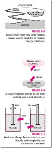
As pointed out earlier, work can easily be converted to other forms of energy, but converting other forms of energy to work is not that easy. The mechanical work done by the shaft shown in Fig. 6–8, for example, is first converted to the internal energy of the water. This energy may then leave the water as heat. We know from experience that any attempt to reverse this process will fail. That is, transferring heat to the water will not cause the shaft to rotate. From this and other observations, we conclude that work can be converted to heat directly and completely, but converting heat to work requires the use of some special devices. These devices are called heat engines.
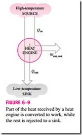
Heat engines differ considerably from one another, but all can be characterized by these statements (Fig. 6–9):
1. They receive heat from a high-temperature source (solar energy, oil furnace, nuclear reactor, etc.).
2. They convert part of this heat to work (usually in the form of a rotating shaft).
3. They reject the remaining waste heat to a low-temperature sink (the atmosphere, rivers, etc.).
4. They operate on a cycle.
Heat engines and other cyclic devices usually involve a fluid to and from which heat is transferred while undergoing a cycle. This fluid is called the working fluid.
The term heat engine is often used in a broader sense to include work- producing devices that do not operate in a thermodynamic cycle. Engines that involve internal combustion such as gas turbines and car engines fall into this category. These devices operate in a mechanical cycle but not in a thermodynamic cycle since the working fluid (the combustion gases) does not undergo a complete cycle. Instead of being cooled to the initial temperature, the exhaust gases are purged and replaced by fresh air-and-fuel mixture at the end of the cycle.
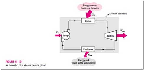
The work-producing device that best fits into the definition of a heat engine is the steam power plant, which is an external-combustion engine. That is, combustion takes place outside the engine, and the thermal energy released during this process is transferred to the steam as heat. The schematic of a basic steam power plant is shown in Fig. 6–10. This is a rather simplified diagram,
and the discussion of actual steam power plants is given in later chapters. The various quantities shown on this figure are as follows:
Qin = amount of heat supplied to steam in boiler from a high-temperature source (furnace)
Qout = amount of heat rejected from steam in condenser to a low-temperature sink (the atmosphere, a river, etc.)
Wout = amount of work delivered by steam as it expands in turbine
Win = amount of work required to compress water to boiler pressure
Notice that the directions of the heat and work interactions are indicated by the subscripts in and out. Therefore, all four of the described quantities are always positive.
The net work output of this power plant is simply the difference between the total work output of the plant and the total work input (Fig. 6–11):
A portion of the work output of a heat engine is consumed internally to maintain continuous operation.
The net work can also be determined from the heat transfer data alone. The four components of the steam power plant involve mass flow in and out, and therefore they should be treated as open systems. These components, together with the connecting pipes, however, always contain the same fluid (not counting the steam that may leak out, of course). No mass enters or leaves this combination system, which is indicated by the shaded area on Fig. 6–10; thus, it can be analyzed as a closed system. Recall that for a closed system undergoing a cycle, the change in internal energy !JU is zero, and therefore the net work output of the system is also equal to the net heat transfer to the system:
Thermal Efficiency
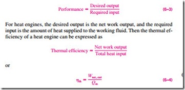
In Eq. 6–2, Qout represents the magnitude of the energy wasted in order to complete the cycle. But Qout is never zero; thus, the net work output of a heat engine is always less than the amount of heat input. That is, only part of the heat transferred to the heat engine is converted to work. The fraction of the heat input that is converted to net work output is a measure of the performance of a heat engine and is called the thermal efficiency hth (Fig. 6–12).
Performance or efficiency, in general, can be expressed in terms of the de- sired output and the required input as (Fig. 6–13)
since Wnet, out = Qin – Qout.
Cyclic devices of practical interest such as heat engines, refrigerators, and heat pumps operate between a high-temperature medium (or reservoir) at temperature TH and a low-temperature medium (or reservoir) at temperature TL. To bring uniformity to the treatment of heat engines, refrigerators, and heat pumps, we define these two quantities:
QH = magnitude of heat transfer between the cyclic device and the high-temperature medium at temperature TH
QL = magnitude of heat transfer between the cyclic device and the low-temperature medium at temperature TL
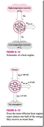
Notice that both QL and QH are defined as magnitudes and therefore are posi- tive quantities. The direction of QH and QL is easily determined by inspection. Then the net work output and thermal efficiency relations for any heat engine (shown in Fig. 6–14) can also be expressed as
The thermal efficiency of a heat engine is always less than unity since both QL and QH are defined as positive quantities.
Thermal efficiency is a measure of how efficiently a heat engine converts the heat that it receives to work. Heat engines are built for the purpose of converting heat to work, and engineers are constantly trying to improve the efficiencies of these devices since increased efficiency means less fuel consumption and thus lower fuel bills and less pollution.
The thermal efficiencies of work-producing devices are relatively low. Ordinary spark-ignition automobile engines have a thermal efficiency of about 25 percent. That is, an automobile engine converts about 25 percent of the chemical energy of the gasoline to mechanical work. This number is as high as 40 percent for diesel engines and large gas-turbine plants and as high as 60 percent for large combined gas-steam power plants. Thus, even with the most efficient heat engines available today, almost one-half of the energy sup- plied ends up in the rivers, lakes, or the atmosphere as waste or useless energy (Fig. 6–15).
Can We Save Qout?
In a steam power plant, the condenser is the device where large quantities of waste heat is rejected to rivers, lakes, or the atmosphere. Then one may ask, can we not just take the condenser out of the plant and save all that waste energy? The answer to this question is, unfortunately, a firm no for the simple reason that without a heat rejection process in a condenser, the cycle cannot be completed. (Cyclic devices such as steam power plants cannot run continu- ously unless the cycle is completed.) This is demonstrated next with the help of a simple heat engine.
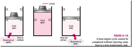
Consider the simple heat engine shown in Fig. 6–16 that is used to lift weights. It consists of a piston-cylinder device with two sets of stops. The working fluid is the gas contained within the cylinder. Initially, the gas tem- perature is 30°C. The piston, which is loaded with the weights, is resting on top of the lower stops. Now 100 kJ of heat is transferred to the gas in the cylinder from a source at 100°C, causing it to expand and to raise the loaded piston until the piston reaches the upper stops, as shown in the figure. At this point, the load is removed, and the gas temperature is observed to be 90°C. The work done on the load during this expansion process is equal to the in- crease in its potential energy, say 15 kJ. Even under ideal conditions (weight- less piston, no friction, no heat losses, and quasi-equilibrium expansion), the amount of heat supplied to the gas is greater than the work done since part of the heat supplied is used to raise the temperature of the gas.
![]() Now let us try to answer this question: Is it possible to transfer the 85 kJ of excess heat at 90°C back to the reservoir at 100°C for later use? If it is, then we will have a heat engine that can have a thermal efficiency of 100 percent under ideal conditions. The answer to this question is again no, for the very simple reason that heat always flows from a high-temperature medium to a low-temperature one, and never the other way around. Therefore, we cannot cool this gas from 90 to 30°C by transferring heat to a reservoir at 100°C. In- stead, we have to bring the system into contact with a low-temperature reservoir, say at 20°C, so that the gas can return to its initial state by rejecting its 85 kJ of excess energy as heat to this reservoir. This energy cannot be recycled, and it is properly called waste energy.
Now let us try to answer this question: Is it possible to transfer the 85 kJ of excess heat at 90°C back to the reservoir at 100°C for later use? If it is, then we will have a heat engine that can have a thermal efficiency of 100 percent under ideal conditions. The answer to this question is again no, for the very simple reason that heat always flows from a high-temperature medium to a low-temperature one, and never the other way around. Therefore, we cannot cool this gas from 90 to 30°C by transferring heat to a reservoir at 100°C. In- stead, we have to bring the system into contact with a low-temperature reservoir, say at 20°C, so that the gas can return to its initial state by rejecting its 85 kJ of excess energy as heat to this reservoir. This energy cannot be recycled, and it is properly called waste energy.
We conclude from this discussion that every heat engine must waste some energy by transferring it to a low-temperature reservoir in order to complete the cycle, even under idealized conditions. The requirement that a heat engine exchange heat with at least two reservoirs for continuous operation forms the basis for the Kelvin–Planck expression of the second law of thermodynamics discussed later in this section.
The Second Law of Thermodynamics: Kelvin–Planck Statement
We have demonstrated earlier with reference to the heat engine shown in Fig.
6–16 that, even under ideal conditions, a heat engine must reject some heat to a low-temperature reservoir in order to complete the cycle. That is, no heat engine can convert all the heat it receives to useful work. This limitation on the thermal efficiency of heat engines forms the basis for the Kelvin–Planck statement of the second law of thermodynamics, which is expressed as follows:
It is impossible for any device that operates on a cycle to receive heat from a single reservoir and produce a net amount of work.
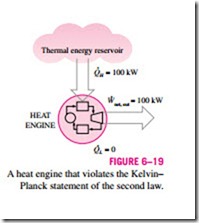
That is, a heat engine must exchange heat with a low-temperature sink as well as a high-temperature source to keep operating. The Kelvin–Planck statement can also be expressed as no heat engine can have a thermal efficiency of
100 percent (Fig. 6–19), or as for a power plant to operate, the working fluid must exchange heat with the environment as well as the furnace.
Note that the impossibility of having a 100 percent efficient heat engine is not due to friction or other dissipative effects. It is a limitation that applies to both the idealized and the actual heat engines. Later in this chapter, we develop a relation for the maximum thermal efficiency of a heat engine. We also demonstrate that this maximum value depends on the reservoir temperatures only.
