COMPRESSOR CLASSIFICATION AND SELECTION
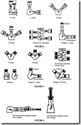
Some of the various methods of compressing gas and air are shown in Figure I. See also ISO 5390. Reciprocating compressors can be further classified as in Figures 2, 3 and 4 according to the arrangement of the cylinders.
Alternative forms of classification are possible, eg according to the motive power which drives the compressor – electric motor, diesel or petrol engine; the type of gas to be compressed; the quality of the compressed medium- the degree of freedom from moisture and oil (as for example might be required in a food processing plant or for underwater breathing supplies); the type of cooling- air or water and so on.
In choosing the correct compressor for a given installation, the following factors must be taken into account:
• Maximum, minimum and mean demand. If there is an intermittent requirement for air, but a large compressor set is needed to cater for peak requirements, the
Vertical with stepped piston (two-stage)
installation can be very uneconomic to opemte unless the control system is well designed. There may be a maximum placed on the power (electricity or gas) consumption. Depending upon the characteristics of the peak demand (ie whether it is long or short term), it may be appropriate to consider a large air receiver as an economic alternative to a larger compressor.
• Ambient conditions- temperature, altitude and humidity. At high altitude, because of the reduced air density, the compressor efficiency and capacity is reduced. High humidity can result in large quantities of water which have to be disposed of.
• Methods of cooling available- availability of cooling water or ambient tempera ture for air cooling. The possibility of using the waste heat for space heating or for process heating should be considered.
• Environmental factors- noise and vibration. Special foundations may be required, particularly with reciprocating compressors.
• Requirements for skilled maintenance personnel.
The actual means chosen for compressing the air is probably less important to the purchaser of a complete unit than is the purchase price and running costs. For small
compressors used on construction sites or for intermittent stationary use, initial cost is the important parameter. For large, permanent, factory installations, running costs (particu larly the off-load costs) are more important. The development of sophisticated methods of control allows almost any kind of compressor to be used efficiently. This means that the emphasis shifts from the compressor per se to the characteristics of the complete packaged installation. Figure 5 shows the broad map of application of the various types; there is much overlap. Table Iis a broad description of characteristics. It should not be taken to give clear boundaries between the different types.
Reciprocating compressors
Reciprocating compressors are suitable for operating over a very wide range of speeds, with a practical maximum of about I0 bar delivery pressure from a single-stage unit, and up to 70 bar for a two-stage machine. Multi-stage reciprocating compressors may be built for special purposes capable of supplying delivery pressures up to and in excess of700 bar. By carefully selecting the number of stages, the designer can also produce a machine which approaches the ideal or isothermal compression curve more closely than with any other type, with the possible exception of very large volume axial flow compressors (see the chapter on Compressor Performance). In the double-acting compressor the space on the other side of the cylinder is enclosed and so both sides are used for compression, giving two compression strokes for each revolution ofthe crank shaft. Alternatively, one side of the piston may be used for one stage and the other for the second stage in a two stage compressor. Individual cylinders may be also used for multi-stage compression, disposed in a number of arrangements.
Most reciprocating compressors are single-stage or two-stage, ranging from fractional horsepower units to very large machines with input requirements of the order of 2250 kW. The smaller compressors are usually single stage of a single or V-twin layout with air cooled cylinders and are powered by electric motors.
Intermediate sizes comprise a variety of different configurations. Vertical compressors may comprise one or more cylinders in line, ‘V’, ‘W’ and ‘H’ arrangements for multi cylinder units, and also ‘L’ configuration which has both vertical and horizontal cylinders disposed about a common crankshaft. The angled arrangement of cylinders offers certain advantages, notably reduced bulk and weight and superior machine balance (since with careful design the primary forces can be accurately balanced). The ‘L’ configuration with a vertical low pressure cylinder and a horizontal high pressure cylinder is advantageous for larger machines, facilitating installation, assembly, maintenance and dismantling. Larger reciprocating compressors are commonly horizontal double acting, tandem or duplex. Basic two-stage units are shown in Figure 2. Variations include transferring the side thrust by means of a crosshead. When the space under the piston is used, it is essential to use a crosshead to convert the rotary action of the crankshaft into reciprocating motion in order to obtain a satisfactory seal of the piston rod where it passes through the compression chamber. The crosshead ensures that all the side thrust component from the crank shaft is taken by the crosshead guide and not transferred to the piston and cylinder. Single-acting reciprocating compressors are normally of the trunk piston type, whilst differential-piston double-acting compressors can be of either type – see Figure 3.
Differential or stepped pistons may also be used as shown in Figure 4. Here one stage of compression takes place in the annular space between the shoulder of the piston and the corresponding shoulder in the cylinders.
Figures 2 to 4 also show designs where a compressor piston is connected to the same crank as the reciprocating engine which drives it. A common arrangement uses three cylinders of a four-cylinder block to form the engine, whilst the fourth cylinder forms the compressor cylinder. This is a convenient way of balancing the forces with a single cylinder compressor.
Figure 6 shows the pattern of reciprocating air compressors in industrial service, according to a recent survey. This represents most of the industrial units in service. For special purposes, as mentioned above, compressors are found well outside the range indicated. The versatility of reciprocating compressors means that they are the most common of all types. The disadvantages of reciprocating compressors are:
• They require special foundations to cater for the unbalanced inertial forces of the reciprocating pistons and connecting rods.
• The maintenance they need has to be done by skilled personnel.
• The inlet and delivery valves are prone to failure.
• The discontinuous flow of the compressed medium can cause vibrational resonance in the delivery passages and the distribution system.
In mobile compressors and in the medium range of stationary compressors, reciprocating compressors tend to have been superseded in recent years by screw and sliding vane designs in oil flooded and dry versions. They still maintain their dominance for large stationary (factory) applications
Reciprocating compressors for oil-free applications
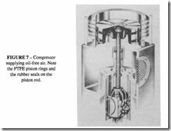
For oil-free applications, special precautions have to be taken. Figure 7 shows how particular designs produce a high degree of cleanliness in the air. No lubrication is necessary in the upper cylinder because the pistons are fitted with PTFE rings; the combination of these rings, austenitic liners and a crosshead guide to minimise piston side loads extends operating life without complicating maintenance. To prevent oil entering the cylinder, a distance-piece incorporating rubber seals is fitted between each cylinder and crankcase. Pure air is produced straight from the compressor without requiring further separation equipment.
An alternative to PTFE piston rings is the use of a labyrinth seal on the piston. Fine grooves are cut in the cylinder wall and the piston skirt, and usually on the piston rod as well.
Valves for reciprocating compressors
One feature of a reciprocating compressor, which is unique to it, is the provision of check valves in the cylinder head. The delivery pressure is detennined by the spring force behind the delivery valve and the pressure in the delivery passage . This is in contrast to a rotary compressor where the shape of the rotor casing alone controls the pressure. Inlet valves open when the cylinder pressure is lower than ambient, delivery valves open when the pressure in the cylinder equals the set pressure. The convenience of this is that the delivery pressure can be changed by modifying the valves only, rather than replacing the compressor casing.
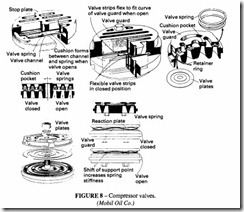
Compressor valves are mostly of the plate type of design as illustrated in Figure 8.
Detailed designs differ but they mostly consist of one or more flat ring-shaped plates backed by helical or flat springs. Valve design is a high art, and valves are best obtained from specialist manufacturers. Valves have to operate very quickly in response to the pressure difference, so the dynamic mass has to be kept low, there has to be a minimum of flow losses, and they must be capable of withstanding the impact forces at the end of the stroke.
Traditionally compressor valves have been made of steel or high grade iron, but there have recently been developed glass fibre reinforced plastics with a high degree of stability under the rapid impact conditions and high temperatures experienced in this duty. Polyetheretherketone (PEEK) has been successfully used for this purpose. This material retains good physical properties (strength and stability) up to 200°C and has lower water absorption properties than other thermoplastics.
Rotary screw compressors
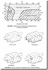
Figure 9 shows the distribution of screw units. It can be compared with Figure 6.
Undoubtedly the most common form of rotary positive displacement compressor is the helical screw compressor, developed primarily by the Swedish companies SRM and Atlas
Copco but now available from a number of manufacturers. The compressive cycle is illustrated in Figure 10.
Rotary screw compressors employ two intermeshing rotors with helical lobes. As the rotors revolve, the space between the unmeshing rotors increases, into which inlet air is admitted. On completion of the filling operation the inlet faces of the two rotors pass the inlet port and the air is sealed in the casing. With continued rotation the flute volume between the two rotors decreases, compressing the air. Compression increases with continued rotation until the built-in pressure ratio is reached and the air is discharged through the delivery port.
Screw compressors can be either oil-flooded or oil-free. Oil-flooded types rely on a substantial volume of oil injected into the compression space. This oil serves a number of purposes: it seals the clearance gaps between the screws and the casing; it lubricates the drive between the male and female screws; and it assists in extraction of the heat of compression.
Dry oil-free types cannot permit a drive to take place between the screws so there has to be external gearing. Some designs incorporate water injection. All-metal screws cannot be adequately lubricated by water so these types also require external gearing. There is an interesting new development in water-lubricated screws in which the screws themselves are made of a ceramic material fastened to a steel shaft. These screws have to be made very accurately in a special mould because only a limited amount of machining after manufac ture is possible. They are finally run together in sacrificial bearings to achieve the final shape.
Whether the screws are water or oil-flooded, it will be apparent that in order to minimise leakage losses, the clearance between the screws has to be kept to a minimum at all rotational positions. The generation of the mathematical forms necessary to produce this minimum clearance and the subsequent manufacturing techniques are the secrets of efficient screw compressor technology.
A characteristic of rotary screws is that the power absorbed by the male rotor is about 95% of the total with the remaining 5% absorbed by the female rotor. The female rotors can be looked upon as being primarily rotary valves. Because of this power distribution between the rotors, it is customary to connect the male rotor (through gearing if necessary) to the prime mover. The screws are not designed as driving gears, but 5% is well within their capacity.
Oil-flooded and dry types each have their own advantages and disadvantages. Dry screw units can only have a limited pressure increase per stage (a maximum of about 3: I), otherwise the temperature increase would be excessive. Oil-flooded screws on the other hand can accommodate a normal pressure ratio of 8: I, and often as high as 13:I.
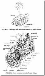
The total leakage flow path is larger than in a corresponding reciprocating compressor. In addition to the clearance between the rotors themselves and between the rotors and the casing, there is also the “blow hole”, which is the triangular hole formed at the intersection of the two rotors and the casing cusp (Figure 11). It is not possible to have anything like a piston ring to seal the gaps. The leakage flow is the same whatever the operating frequency (it depends only on the pressure difference) so in order to keep the percentage loss through leakage to a minimum, the rotational frequency has to be high. This is true
for both oil-flooded and dry types, but as there is no assistance from the oil in sealing the dry screw, its optimum frequency has to be much higher. The churning of the oil inside the compression chamber represents a power loss and a resultant fall in efficiency. There is an optimum operating speed at which such losses are balanced by losses through leakage. For oil-flooded units, the optimum linear peripheral speed of the screw is about 30m/sand for dry screws about I 00 m/s. For a typical oil-flooded air-end see Figure 12.
When driven from an internal combustion energy or an electric motor, a step-up gear drive (of about 3:1 in the smaller sizes of the oil-flooded types and about 10:I in the dry types) is required. This is usually separate from the gearing provided to keep the two rotors apart. The latter has to be very carefully manufactured and set: the backlash in the timing gears has to be much less than that between the rotors, which itself has to be kept small to reduce leakage. A technique frequently adopted is to coat the rotors with a thin layer of plastic (PTFE or similar), so that on initial assembly the rotors are tight; after a careful running-in period the coating rubs off locally to form a good seal.
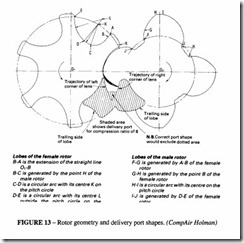
Much effort has been put into the careful design of the rotor profile. Originally rotors were part-circular in shape, but now much more mathematically complex shapes are favoured. Figure 13 shows a widely adopted shape. Note that the lobes are asymmetrical
in cross section. This ensures efficient compression with a limited leakage area. Many attempts have been made over the years to produce more efficient meshing profiles. The rewards likely to be obtained through the exercise of such ingenuity are likely to be small, although one of the main motives for producing alternative designs is an attempt to circumvent the strong existing patents.
One feature of the oil-flooded compressor is the necessity for removing the oil after
compression. This is done by a combination of mechanical impingement and filtration. The residual oil left in the air after such treatment is very small (of the order of 5 parts per million)- good for most purposes but not for process equipment or breathing. See Figure 14 for a typical system. For further information see the chapter on Compressor Lubrication.
Diaphragm compressors
Diaphragm compressors are positive displacement, oil-free types. They can be driven mechanically or by hydraulic pressure. Mechanical diaphragm compressors are manufactured in smaller capacities than hydraulically actuated units and consequently overlapping of the two types occurs only over a limited range.
Mechanical units are less expensive to produce, are very compact and can be used on applications involving sub-atmospheric pressures (see Figures 15 and 16).
Hydraulically actuated units are able more easily to generate high pressure than are mechanical units as the latter are usually limited by considerations of bearing loading.
Apart from the fact that the compact form of a diaphragm unit enables it to be directly built into the electric motor or driver (or hydraulic pump in the case of an hydraulically operated machine, the main advantages offered by diaphragm compressors are:
• Complete gas tightness with only static sealing involved.
• Isolation of the gas being handled and thus the possibility of 100% oil-free compressed gas supply.
The main limitations of the type are low delivery rates (to a maximum of about 30 1/min in a single unit) and a limited compression ratio (to about 4.0). The latter limitation applies particularly to mechanically operated diaphragms where the diaphragm itself is normally of synthetic rubber. Hydraulically-operated diaphragm compressors may employ metallic diaphragms and be capable of generating much higher pressures. A further method of obtaining high pressure is to enclose the compressor and driver within a pressure vessel. The vessel is pressurised to a level equal to that present in the inlet. The same pressure is thus present on the underside of the diaphragm, reducing the pressure differential on the diaphragm when working.
Rotary sliding vane compressor
A well-tried, mechanically simple design, Figures 17 and 18. The rotor and the vanes are the only moving parts. The rotor is mounted offset in the casing; as can be seen, the
compression is obtained through this eccentricity. Air is admitted when the crescent shaped chamber is increasing in volume and delivered when the design pressure is reached. As in all other rotary positive displacement types, it has a built-in pressure ratio, dependent on the position of the delivery port.
The rotor is a simple cylinder, with longitudinal slots machined in it, and the vanes can be cut from plate material. These are available in three forms -lubricated, oil-free and oil flooded.
Lubricated types inject an oil mist into the incoming air stream. Alternatively oil can be fed from a reservoir through the shaft or directly into the cylinders. Vanes are made of steel, in which case a floating ring (see below) is required, or of a synthetic fibre material (newer types). The use of synthetic fibre is advantageous in that the lower mass means a smaller centrifugal force.
Oil-free types, suitable for process applications require self-lubricating vanes made from carbon.
Oil-flooded types are similar to screw compressors in that large quantities of oil are injected into the compression space, which then has to be separated out and cooled. As with screw compressors, the oil lubricates, cools and seals. The vanes are made of aluminium, cast-iron or a synthetic fibre material.
The rotational frequency has to be low, otherwise the centrifugal forces on the vanes would cause frictional failure, so a direct motor drive is customary. Wear of the surface of the vanes that contacts the stator can be a problem, but because they are free in their slots, such wear is self-compensatory. Wear on the side of the vanes or on their ends causes a fall in efficiency, and they should be replaced when such wear exceeds the manufacturer’s recommendations.
Medium or large capacity vane compressors running at high speeds normally incorpo rate a method of avoiding contact between the vanes and casing wall in order to reduce wear and minimize frictional losses. One method is to fit restraining or floating rings over the vanes, the internal diameter of these rings being slightly less than the cylinder bore. The difference is calculated to preserve a minimum clearance between the vane tips and the casing walls under operating conditions, see Figure 19.
The rings actually rotate with the vanes but the peripheral speed of each vane tip varies
with the degree of extension. The rings rotate at constant speed. There is some relative motion between vane and rings, but the contact between rotor and rings is essentially a rolling motion.
Low pressure blowers
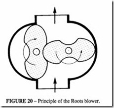
These are meshing rotors suitable for low pressure ratios only. There is no built-in compression ratio, any increase in pressure being achieved by compressing against the back pressure in the system. Such a device is inefficient, its real advantage lying in the simplicity of manufacture. Figures 20 and 21 show an example of this type- the Roots blower.
Two types are available – the single-acting, circular stator, and the double-acting, oval stator. Both are illustrated in Figure 22 . They both have a built-in pressure ratio, but the double-lobe body is more suitable for higher pressures (up to 7 bar). A variety of liquids can be used; water is a common one, but non-corrosive liquids can also be used according to application. The presence of a large quantity of liquid means that churning losses are high, but cooling is very good, so isothermal conditions are approached at the expense of mechanical efficiency. These units are also useful as vacuum pumps.
Rotary tooth compressors
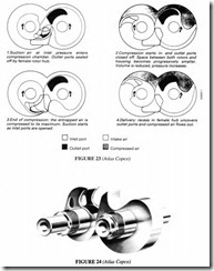
One type is illustrated in Figures 23 and 24. The rotors are parallel in section and are externally meshed through timing gears; there is no possibility of one tooth driving the other as in rotary screws . They are suitable for producing oil-free air. They are available as low pressure single-stage blowers up to 2.5 bar and as two stage compressors up to 7
bar_ They are claimed to be suitable for pressures up to 10 bar_ The rotors are of comparatively simple construction in that they do not require helical machining so they can be made from materials that would otherwise be difficult to manufacture, such as stainless steeL
The inlet and delivery ports are situated in the end plates of the compressor housing with no inlet or delivery valves. There is very little end thrust on the rotating elements, which ensures low bearing loads. With the tooth form shown, there can be no drive between the rotors so there has to be external gearing.
Because of the straight tooth design, and the axial inlet and delivery ports, axial loads on the rings are eliminated. The compressor illustrated has rotor speeds between 3000 and 6000 r/min. Note that in this design, portions of the teeth intersect.
An alternative design has no intersecting part (Figure 25), which makes it closer to a Roots blower. This compressor element can be direct coupled to an electric motor with a rotary speed to 1500 r/min and below.
Turbocompressors
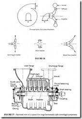
Turbocompressors (or dynamic compressors) convert the mechanical energy of the rotating shaft into kinetic energy of the air as it passes through the unit. The kinetic energy is converted into pressure energy, partially in the impeller and partially in the delivery passage or volute. These compressors are classified according to the path that the air follows in its passage through the machine- in a centrifugal compressor the flow is radial; in an axial unit it is axial; there is also a mixed type in which the flow is both radial and axial; see Figure 26. Turbocompressors are very compact units, producing large volumes of air in a small space. They are mainly found in process industries which require large volumes of oil-free air at a relatively constant rate.
As in other types, compression can take place in stages. The pressure ratio which can be reached in a single stage is limited by the maximum peripheral speed of the impeller. Centrifugal machines normally generate a pressure ratio per stage of 1.5 to 2.0, although with improving technology pressure ratios are increasing. A pressure ratio of 6 can obtained in a 2-stage design. In an axial compressor the compression per stage is limited to about 1.3;they may have up to 20 stages. Centrifugal units may incorporate intercooling between stages, axial units rarely do. Single-stage centrifugal units are frequently used as blowers and exhausters.
Shaft speeds are high- 20 000 r/min is common in industrial units. 100 000 r/min is
found in aircraft engines. At these speeds rolling bearings are unsuitable; plain or tilting pad bearings are necessary. Figure 28 shows a modern single-stage centrifugal unit. It can be seen that the actual compressor forms only a small part of the air end; the major part of the machine is in the step-up gear and the cooler.
Comparison of behaviour of centrifugal and axial compressors
Each type has its own characteristics: axial compressors are suitable for large flow rates only (20 to I 00 m Is); centrifugal units are available supplying from 0.1 to 50 m Is. Axial compressors have a rather better thermodynamic efficiency, but only at the design point; they are susceptible to changes in throughput and pressure. Centrifugal units have good part-load characteristics; the off-load power absorbed is as low as 3%; this makes them particularly suitable for intermittent use and when needed to supply a range of pressures and flow rates. The operating speed of axial compressors is considerably higher than for centrifugal and for this reason combined with the large number of vanes they tend to be noisier.
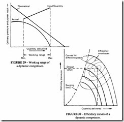
Discharge pressure and volume of air delivered are co-related. If at a given speed the back pressure is reduced, the volume delivered will increase and vice-versa. See Figures 29 and 30.
If the back pressure increases to a value above that generated by the compressor then a condition known as ‘surge’ occurs, and air flow is reversed. If the pressure then drops the pressure starts to deliver again and if this sequence continues serious damage could result. Practical operating limits are therefore terminated by a surging limit, see Figure 30. To avoid surging it is necessary to recycle a part of the compressed volume by means of a by-pass that opens automatically as soon as the surge point is reached. The anti-surge system should be independent of the other means of control and is controlled from the flow rate or the pressure difference. Provision should be made for isolating the compressor from the mains when operating conditions approach the surge point, and for restoring it when the surge pressure has fallen. With the latest forms of computer control it is possible to extend the stable range of both axial and centrifugal types.
Mixed flow units combine some of the advantages of axial and centrifugal units. For a given flow rate the mixed designs have a smaller diameter. There is less turbulence and therefore the efficiency is better. They are mainly used for single-stage compression.

