Types of filters
Some filters are designed to be installed in the pressure line and are normally used in systems where high-pressure components such as valves are more dirt sensitive than the pump. Return line filters are used in systems, which do not have large reservoirs to permit contaminants to settle at the bottom. A return line filter is needed in systems containing close tolerance high-performance pumps. Let us now study some of the common filters normally used in hydraulic systems.
Duplex-type filters
Figure 7.6 shows a filter designed for either a suction line or a pressure line. This is a duplex filter.
A duplex filter, as the name suggests consists of two filters out of which only one is in use all the time. When the filter element gets clogged, the second filter is put to use. Dirty fluid comes into the middle section and passes down through the filter element. The filter element can be of fine gage nylon cloth or wire cloth or finely perforated stainless steel.
From the filter element, the fluid passes out of the unit and into the line. This unit has a ‘telltale’ indicator, which indicates when the filter element is excessively clogged and requires cleaning. If the filter is not cleaned after indication, the fluid bypasses the filter element and there is no filtering action. Such a bypass mechanism is important for a filter because, when the filter element is clogged heavily, the pump in line may get damaged due to starvation of hydraulic fluid.
Edge-type filters
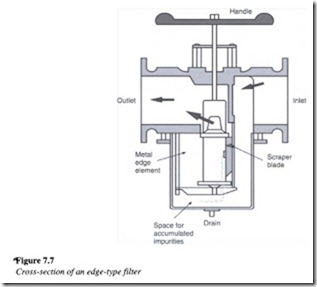
This is also referred to as a full flow filter, which means that all the oil in the system passes through it. Figure 7.7 illustrates an edge-type filter.
The edge-type filter consists of a stack of disks with holes in their center, like flat doughnuts, with very little separation between them. When entering the filter, fluid is guided from the bottom at the outer side of the stack. Before leaving the filter, it comes out of the center of the stack having passed through the disks. Impurities in the oil are left behind on the outer edge of the stack. A scraper blade moves over the outer surface of the stack, wiping off all the dirt collected. The blade is operated manually by means of a handle at the top of the filter housing.
Tell-tale filters
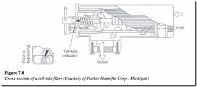
This is a versatile filter, which can be directly welded into a reservoir’s suction and return line or conversely installed in pipes with a maximum pressure of 10 kg/cm2 (142 psi). This filter can remove particles as small as 3 fl. It consists of an indicating element, which
indicates the time when cleaning is required. That is why this filter is referred to as a tell tale filter (Figure 7.8).
The operation of a tell-tale filter is dependent on the fluid passing through the porous media, which traps the contaminants. The tell-tale indicator monitors the pressure differential buildup due to dirt, which gives an indication of the condition of the filter element.
Principle of working
Fluid enters the inlet at the bottom of the tube, passes from the inside to the outside through the filter element and exits at the side outlet. When a new and recently cleaned filter element is fitted in the housing, the tell-tale indicator will indicate that it is ‘clean’.
As dirt deposits on the surface of the element, the pressure differential across the inlet and
outlet of the element rises. The bypass piston senses this difference in pressure. The piston is held seated by a spring. When the element requires cleaning, the pressure differential is high enough to compress the spring, forcing the piston off its seat. The piston movement causes the tell-tale indicator to point towards the ‘needs cleaning’ position.
When the filter element is not cleaned when this signal comes on, the pressure differential
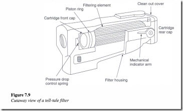
continues to rise, causing the piston to uncover a bypass passage in the cover. This action limits the rise in the pressure differential to a value equal to the spring tension and the fluid bypasses the filter element. A cutaway view of a tell-tale filter is shown in Figure 7.9.
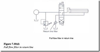
The following schematics show a few of the typical methods used for filtration. Figure 7.10(a) shows the location of a proportional flow filter. As the name implies, proportional flow filters are exposed to only a percentage of the total flow in the system. The primary disadvantage of this type of filtration arrangement is that, there is no positive protection of any specific component within the system and there is no way to know that the filter is dirty.
Strainers
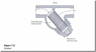
A strainer is a device made of wire mesh screens, which seek to remove large solid particles from a fluid. As part of standard engineering practice, strainers are installed on pipelines ahead of valves, pumps and regulators, in order to protect them from the damaging effects of fluid and other system contaminants.
A common strainer design uses two screens, cylindrical in shape. One cylinder is inside the other and the two are separated by a small space. The outer cylinder is a coarse mesh screen and the inner one is a fine mesh screen. The fluid first passes through the coarse mesh screen and filters the larger particles. It then passes through the fine mesh screen, which blocks the smaller particles. Figure 7.11 shows the cross-sectional view of a typical strainer.
The bottom of the strainer serves as the sump (or pot) for the solids to collect. The strainer can be cleaned out easily at intervals, by two different procedures:
1. The cleanout plug can be removed and the pressure in the line can be used to blow the fixture clean.
2. The large retaining nut at the bottom is to be removed for pulling the mesh out of the strainer in order to clean it and putting it back in line.

