Isolating valves
There are many instances where material has to be transferred, usually under gravity, in batches. The valve is either open or closed and often has to provide an airtight seal. In the gate lock feeder, for example, a pair of valves is required to operate in sequence to feed small batches of material into a pipeline.
Where batches of material have to be fed into blow tanks, the valve has to be cap- able of withstanding the pressure subsequently applied to the blow tank. Of the valves considered above only the dome valve would be appropriate for this type of duty. It finds wide use in this application, particularly with the more difficult granular and abrasive materials.
Butterfly valves
If the material to be handled is not abrasive, the butterfly valve is ideal. They are reasonably priced, require very little headroom, are not too heavy, and are reasonably air- tight. They are widely used in the food and related industries, and in gate lock feeders. They are, however, much too vulnerable for use with abrasive materials, since the valve remains in the flow when it is open.
Disc valves
Disc valves, like butterfly valves, require very little headroom, but like dome valves, they swing completely out of the way of the flow of material. They cut though the material on closing, but generally rely on the subsequent pressure in the vessel below to provide the necessary seal. Their suitability for use will depend very much upon the material to be handled and the application.
Slide valves
Slide valves are the oldest valves in the business, and although they have been improved over the years, the disc valve is a specific development from it. They take up little space and are cheap. A particular application is in terms of back-up. If any of the other more expensive and sophisticated valves fail, and need to be replaced, this can be a very difficult and time consuming task if the valve is holding several hundred tonnes of material in a hopper, and this must be drained out before the valve can be removed for repair or replacement.
Vent line valves
This is a deceptively easy duty, but if it is on a high pressure blow tank handling a material such as fly ash or cement, the valve will have to operate in a very harsh environment. With the venting of high pressure air the air velocity will be very high, albeit for a very short period of time. As a consequence of the turbulence in the blow tank, however, a considerable amount of abrasive dust is likely to be carried with the air. If the material is abrasive then the choice is between a pinch valve and a dome valve. If the material is non-abrasive, a diaphragm valve could be used.
Flow diversion
Flow diverting is a very common requirement with pneumatic conveying systems and can be achieved very easily. Many companies manufacture specific flow diverting valves for the purpose. Alternatively flow diversion can be achieved by using a set of isolating valves. The most common requirement is to divert the flow to one of two alternative routes, typically where material needs to be discharged into a number of alternative hoppers or silos. In this case the main delivery line would be provided with a diversion branch to each outlet in turn.
Diverter valves
There are two main types of diverter valves. In one, a hinged flap is located at the dis- charge point of the two outlet pipes. This flap provides a seal against the inlet to either pipe. The pipe walls in the area are lined with urethane, or similar material, to give an airtight seal, and this provides a very compact and light weight unit.
The author tested a Y-branched diverter valve of this design with silica sand in dilute phase, but it was a disaster. After conveying only 12 tonne of sand, the 4 mm thick bronze flap had a 15 mm diameter hole through it. The urethane lining, however, was in perfect condition. The problem was that the sand was always impacting against the flap. A straight through design with a branch off would have been better, but still not suitable for abrasive materials.
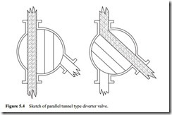
The other main design operates with a tunnel section of pipe between the supply and the two outlet lines. This unit would not be recommended for abrasive materials either. This design, however, should provide a more positive seal for the line not oper- ating, which would probably make it a more suitable valve for vacuum conveying duties. A sketch of a parallel tunnel type diverter valve is presented in Figure 5.4 to illustrate the method of operation.
Isolating valves
Flow diversion can equally be achieved by using a pair of isolating valves, with one placed in the branch, close to the supply pipe, and the other in the supply pipe, just
downstream of the branch. This can be repeated at any number of points along the pipeline. The main disadvantage with this arrangement is that a plug of material will be trapped in the short section of pipeline not in use, which will have to be blown through when the flow direction changes.
If the conveyed material is abrasive, this method of flow diversion would be recommended. Either pinch valves or dome valves would need to be employed for the purpose. With two separate valves, instead of one to operate, care would have to be exercised with the sequencing when changing flow direction.
