Introduction
The use of high pressure systems in pneumatic conveying has been a long and slow development. Part of this was probably due to a misunderstanding of the relationship between high pressure and dense phase conveying. There was very little published information on the subject and few universities, on a worldwide basis, were undertaking research in the area. This was one of the main reasons for the Department of Trade and Industry in the UK commissioning research work in the early 1980s for the preparation of the first edition of this Design Guide.
There was probably also a reluctance to venture into an unknown area, when the rotary valve and positive displacement blower were so dominant. The blow tank was being used, and at high pressure, but it was still very much a batch conveying system with limited demand. With an increasing need for high tonnage flows and long distance conveying, particularly in the cement and coal fired power generation industries, the screw conveyor was developed and became dominant in this market for many years.
Then in the mid-1980s with the start of globalization, and increasing competition in industry, manufacturing companies made advances with both rotary valves and blow tanks. Two manufacturers in Europe developed a rotary valve that would operate with air supply pressures greater than two bar gauge, and the use of lock hoppers was introduced with blow tanks so that they could operate continuously at high pressure.
Today, most companies manufacturing rotary valves offer high pressure rotary valves for a very wide range of materials, although they will be found most widely in use in the chemicals industry. The initial impetus for the continuously operating blow tank was to try to take over the market for high pressure screw feeders and this was successful to a large extent. Demand for the screw feeder has fallen significantly and that for the continuously operating blow tank has been well established.
Lock hoppers
Although the concept of lock hoppers has been known for a very long time, and has been utilized in many other areas of industry, it has been slow in being adopted in pneumatic conveying. It is not only blow tanks that can benefit from their use, however. As the lock hopper enables the feeder to operate without a pressure drop existing across it, conventional rotary valves and conventional screw feeders can also be used for the high pressure conveying of materials. These feeders, of course, have the advantage that they are positive displacement feeders so that feed rate control can be achieved simply by varying the speed of operation. Venturi feeders can also operate at significantly higher pressures.
Screw feeders
The simple screw feeder was introduced in Chapter 3 (Figure 3.15). Although ideal for feeding negative pressure conveying systems, it is just not appropriate for positive pressure conveying applications because of the air leakage problems. There is nothing in the design that will provide the necessary sealing to prevent air leakage with positive pressure operation.
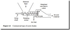
The simple screw feeder, however, was developed by several companies into a device that can feed successfully into conveying lines at pressures of up to 2.5 bar gauge. One such device, which was manufactured by the Fuller Company of the USA, is known as a Fuller–Kinyon pump. In Germany, Claudius Peters developed a similar Peters pump at about the same time. A sketch of this type of screw feeder is given in Figure 4.1.
The main feature of these screw feeders is that the screw decreases in pitch along its length. By this means the material to be conveyed is compressed to form a tight seal in the barrel. These feeders used to be widely used in the cement industry, and for fly ash conveying in power stations. The material is fed from the supply hopper and is advanced through the barrel by the screw.
Since the screw pitch decreases towards the outlet, this compacts the material as it passes through the barrel. This is sufficient to propel the plug through the pivoted non- return valve at the end of the barrel and into a chamber into which air is continuously supplied through a series of nozzles. A pressure drop of about 0.5 bar must be allowed for the air across these nozzles, which adds significantly to the power requirement. A screw having a decreasing pitch does, however, require a very high power input for a given feed rate.
It is partly because of the high energy requirements, particularly for the screw, that the device has gone out of favour. It is probably equally due to the fact that as the materials that are mostly conveyed, such as cement and fly ash, are very abrasive, wear problems occur with the screw, adding to the maintenance problems. Being capable of
continuous operation and having a high pressure capability means that it is often used in closed loop conveying systems, when a high operating pressure is required.
For high pressure operation the device is only suitable for materials that can be com- pressed, which generally restricts their use to materials that have very good air retention properties, such as cement and fly ash. These are Group A materials in Geldart’s classi- fication shown in Figure 2.17. Due to their very good air retention capability, their bulk density can be increased by up to 50 per cent simply by means of vibration. With Group B materials, however, the increase in bulk density achieved is typically about one- third of this, which is insufficient. The seal against the high pressure conveying air is effected in the reducing pitch screw. The required degree of compression cannot be obtained with granular materials (Group B) and so air will leak through the feeder at high operating pressure.
Incoming search terms:
- lock used in pnuematic equipments with high pressure
- 3 chamber lock hopper pumping
- feed screw pump with hopper
- rotary lock for tank hoppers
