Pipeline bore
This rapid transition has also been accentuated by the small bore pipeline, since the increase in the air only pressure drop represents a significant proportion of the total pressure drop available for a long pipeline. This effect is illustrated with Figure 14.6. Stepping the pipeline to a larger bore part way along its length will also help in extending dense phase conveying capability to longer distances.
Empty line pressure drop
For the scale up of the conveying characteristics with respect to pipe bore, the change in datum for the empty line will also have to be taken into account. Data for empty lines, 95 m long, of different bore is given in Figure 14.6. In a similar manner to that for Figure 14.3, the data for Figure 14.6 was also obtained from the relationship presented in Equation (14.1). The variation of pressure drop with air flow rate for the 81 mm bore pipeline is included and so the change in datum can be obtained by taking the differ- ence between the 81 mm and the required bore of pipeline. It will be seen from this that the air only pressure drop element reduces significantly with increase in pipeline bore.
Scaling model
Scale up of material flow rate with respect to pipeline bore can be carried out with a reasonable degree of accuracy, if the extrapolation is not too great, on the basis of pipe cross-sectional areas:
Working model
The working form of this scaling model is:
where subscripts 1 and 2 relate to the appropriate pipe bores of the two pipelines. It is for this reason that the air mass flow rate axis in Figure 14.6 is in terms of the air required for the 81 mm bore pipeline X (d2/81)2. Conveying air velocities scale up exactly and so a common axis can be used. For the scaling up of the conveying characteristics in Figure 14.1, with the materials conveyed over 95 m through an 81 mm bore pipeline, to a pipeline of larger bore, the datum pressure drop should first be changed throughout by the appropriate values obtained from Figure 14.6. Material mass flow rates for a given air mass flow rate and conveying line pressure drop are then scaled in the ratio of (d2/81)2.
Scaling procedure
The scale up of the conveying characteristics for the two materials conveyed over 95 m through the 81 mm bore line to a 100 mm bore line is presented in Figure 14.7.
The influence of minimum conveying conditions, for the cement, has not had the radical effect that was obtained with the scale up in terms of conveying distance. This is because the air flow rate is scaled up by essentially the same model as the material flow rate. The scale up in terms of pipe bore produces a set of curves that are basically geometrically similar for both materials, apart from the slight change due to the shift
in datum for the empty line pressure drop relationship. There is, therefore, little difference in minimum conveying conditions for different pipeline bores, since similar solids loading ratios result at the same values of conveying line pressure drop. Air mass flow rates are totally different, of course, as these have been scaled up in proportion to the cross-sectional area of the pipeline.
Scaling to larger bores
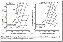
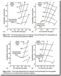
The results of scaling the conveying characteristics over a distance of 95 m to larger bore pipelines are presented in Figures 14.8–10. These are for pipeline bores of 125, 150 and 200 mm. In each case only that part of the conveying characteristics between material flow rates of approximately 30 and 50 tonne/h, for the cement, and 8 and 16 tonne/h, for the potassium sulphate, have been included.
In the vast majority of cases a system has to be designed to achieve a given flow rate of material and this is why the scaling of the conveying characteristics has been limited to narrow bands of material flow rate, rather than complete sets of data as with conveying distance. With a range of pipeline bores considered it will be possible to illustrate the inter-relating effects of pipeline bore and conveying line pressure drop on material flow rate for a given system specification. It should be noted that since the same length of the air flow rate axis has been used in each case, this has distorted the shapes of the curves and has produced very steep lines of constant solids loading ratio as a consequence.
If 40 tonne/h of cement and 12 tonne/h of potassium sulphate are considered, by way of example, the influence of pipeline bore on the type of conveying system can be illustrated with these two sets of conveying characteristics. With the 81 mm bore
pipelines, in Figure 14.1, both materials could be conveyed at these flow rates, but high pressure blow tank systems would be required. With the 100 mm bore pipelines, in Figure 14.7, air supply pressures are down to about two bar gauge and so there is now a possible choice between high pressure rotary valves (for the non-abrasive potassium sulphate), screw pumps (for the air retentive cement) and blow tanks for feeding the materials.
There is a further reduction in air supply pressure with the increase to 125 mm, in Figure 14.8. With an abrasive material such as cement this would be a better choice for use in conjunction with a screw pump than the higher pressure required for the 100 mm bore line. With the 200 mm bore pipeline (Figure 14.10) pressure requirements are in the range where low pressure rotary valves could be considered, and in the case of potassium sulphate the pressure drop is such that a vacuum conveying sys- tem could be considered for the duty.
Influence on conveying parameters
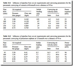
A comparison of these sets of conveying characteristics will show that as the pipeline bore increases, the air flow rate required increases, and the solids loading ratio and conveying line pressure drop decrease for a given material flow rate. This is shown in Tables 14.1 and 14.2 where a comparison is made of these parameters for the conveying of the cement at 40 tonne/h and the potassium sulphate at 12 tonne/h. In each case the data is based on an air flow rate 20 per cent greater than the minimum value corres- ponding to the given material flow rate. In both cases this represents a satisfactory margin for design purposes.
These tables show that there is a wide range of air supply and pipeline bore combinations that are capable of meeting any given duty for a material. For the cement there is an almost eightfold increase in air flow rate required, with a corresponding reduction in solids loading ratio; and for the potassium sulphate there is a sixfold reduction in air supply pressure, over the range of pipe bores considered.
Air supply pressure
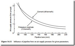
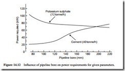
To illustrate the point with regard to the influence of pipeline bore on air supply pressure, the data from Tables 14.1 and 14.2 is presented graphically in Figure 14.11.
With a wide range of pipeline bore and air supply pressure combinations being capable of achieving a given material flow rate, the obvious question is which pipeline bore or air supply pressure results in the most economical design? Plant capital costs could vary considerably, for with different pipeline bore and air supply pressures there are corresponding differences in feeder types, filtration requirements and air mover types, apart from widely different pipeline costs, and so a major case study would need to be carried out. Power requirements, and hence operating costs, however, are largely dependent upon the air mover specification and so these can be determined quite easily by using Equation (6.6).
Power requirements
The approximate power requirements for the cases considered are given in Tables 14.1 and 14.2, and they are presented graphically in Figure 14.12. In most cases the power required for the air mover represents the major part of the total system power requirement, although for screw pumps a major allowance must also be made for the screw drive. Figure 14.12 presents an interesting trend for both of the materials considered. For the cement the smallest bore pipeline is clearly the best, but for the potassium sulphate it is the largest bore pipeline.
For the potassium sulphate the decrease in power requirements with increase in pipeline bore can be explained in terms of the decrease in velocity through the pipeline. With a conveying line inlet air pressure of 3.2 bar gauge the conveying line exit air velocity will be about 68 m/s, and this reduces to 27 m/s with the much lower air supply pres- sure required for the 200 mm bore pipeline. Pressure drop increases significantly with increase in conveying air velocity and so the pipeline with the lowest velocity profile will generally give the lowest power requirement for a material such as potassium sulphate.
For the cement the increase in power with increase in pipeline bore can also be explained in terms of velocity profiles, but in this case it is values of conveying line inlet air velocity that are relevant. Since cement is capable of being conveyed in dense phase, the relationship between minimum velocity and solids loading ratio dictates. In an 81 mm bore pipeline the inlet velocity is only 4.2 m/s, since the solids loading ratio is 109. In the 200 mm bore pipeline the solids loading ratio is reduced to 14 and so the inlet air velocity is 12.0 m/s.


