Material grade influences
It has already been mentioned that many materials come in a variety of grades and that conveying capability and performance can vary widely with different grades of the same material. A number of cases are presented here to highlight this particular problem and to show the potential magnitude of the differences.
Alumina
Alumina comes in a variety of grades and these grades are often referred to as sandy and floury. The pipeline used for conveying such grades is shown in Figure 13.20 for reference.
The pipeline was 47 m long and of 53 mm bore. A high pressure bottom discharge blow tank was used to feed the materials into the pipeline. Tests were undertaken with
air supply pressures up to 3.2 bar gauge for each material. Conveying characteristics for the two grades of alumina tested are presented in Figure 13.21.
For the sandy alumina the minimum conveying air velocity was in the range of 10–12 m/s and this was dilute phase suspension flow. The high value of solids loading ratio achieved was due to the fact that the material could be conveyed at 10 m/s at high pressure, combined with the very high pressure gradient available. A pressure drop of
3.2 bar in a pipeline only 47 m long gives an exceptionally high pressure gradient, but despite this the material could only be conveyed in dilute phase. With the sandy alumina the minimum conveying air velocity was down to 3 m/s and solids loading ratios of 200 were achieved. This floury grade of alumina could be conveyed with a conveying line inlet air velocity of 11 m/s in dilute phase.
By-pass system performance
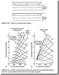
Probably the majority of the alumina that is manufactured is sandy grade and consequently by-pass systems are widely used for its conveying. The innovatory conveying systems were considered in Chapter 2 and a sketch given of various pipeline systems employed in Figure 2.14 is repeated here as Figure 13.22 for reference. The internal by-pass system is probably the most widely used, with flutes along its length as shown.
In a programme of work undertaken with a different grade of alumina in pipeline no. 9, a porous tube was used instead of a fluted pipe [5]. A porous pipe has the advan- tage of allowing the flow of air into and out of the by-pass pipe when and wherever it is required. The results of tests undertaken with the alumina in the pipeline without the
by-pass pipe are presented in Figure 13.23a. Conveying characteristics for the alumina conveyed through the pipeline with a porous pipe inserted along its length are pre- sented in Figure 13.23b.
The conveying characteristics for the alumina in Figure 13.23a compare directly with those for the alumina in Figure 13.21a. The material for Figure 13.23a is a dif- ferent grade of sandy alumina and tests were only undertaken with material flow rates of up to about 10 tonne/h, but it will be seen that they are very similar. Lines of constant conveying line inlet air velocity have been superimposed on the conveying characteristics in Figure 13.23 for reference.
The conveying characteristics for the same material as presented in Figure 13.23a and conveyed through the same pipeline (pipeline no. 9), but with the insertion of the by-pass pipe, are presented in Figure 13.23b.The first point to note is that the material flow rate did not get to 10 tonne/h even with an increase in conveying line pressure drop to 2.4 bar. With the internal by-pass pipeline, at least 10 per cent of the available cross-sectional area for material flow is lost. This will also influence the air only pres- sure drop value for the pipeline. In addition there is an increase in wall surface area and so the wall friction loss will increase. As a consequence an approximate 40 per cent increase in pressure drop is required to achieve the same material flow rate.
Another major difference, of course, is the fact that the material will convey successfully in the pipeline with the porous by-pass pipe at a very low velocity. The resulting conveying characteristics are very similar in form to those of both the poly- ethylene pellets and the nylon pellets presented earlier in this chapter. It is recognized that the pelletized materials are naturally conveyed in plug flow, and as it is claimed that the object of the by-pass pipe is to split the flow up into plugs, it is perhaps not surprising that the conveying characteristics should be very similar. This does, how- ever, mean that not only is the material flow rate reduced because of the loss in flow section area, it is also reduced as a consequence of the change in slope of the constant pressure drop lines at low air flow rates.
It will be noticed that there is no difference between the maximum values of solids loading ratio achieved between these two sets of conveying characteristics presented in Figure 13.23. That of 35 for the dilute phase conveying of a material that can only be conveyed in dilute phase suspension flow is typical of that achieved with other materials presented here when a high pressure gradient is available for conveying. That of 35 is also typical of the values reported for the dense phase conveying of pelletized materials in low velocity plug type flow.

