Pipeline bends
The influence of pipeline bends has long been an issue of some considerable doubt. This is mainly due to the problems of obtaining the necessary data, as discussed in Section 5.2.4.3. In the notes on pipeline bends in Section 11.6.4, actual pressure drop values were presented, in the form of conveying characteristics in Figure 11.16 and this showed a range of values from 50 to 170 m bar per bend. Ideally an equivalent length, in terms of horizontal pipeline, is required for pipeline bends.
Equivalent length
Such an analysis was carried out specifically for the Pneumatic Conveying Design Guide. Two pipelines and two different materials were used in a major programme of
tests. The two pipelines used were of approximately the same length but contained a different number of bends. By this means the sets of conveying characteristics produced could be compared and the differences between them could reasonably be attributed to the difference in the number of bends.
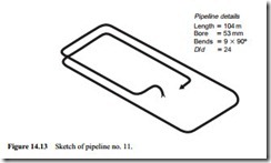
One of the pipelines used was that presented in Figure 13.4 (pipeline no. 7). This was 101 m long, of 53 mm bore and contained seventeen 90° bends. The other pipeline used was 104 m long, also of 53 mm bore but contained only nine 90° bends and is shown here as pipeline no. 11 in Figure 14.13 for reference. All of the bends in the two pipelines were of the same geometry, having a bend diameter, D, to pipe bore, d, ratio of 24:1, and all the bends were preceded by a sufficient length of straight horizontal pipeline to ensure that the particles had been accelerated to their terminal velocity before impact with the bend.
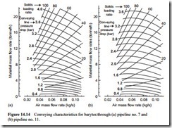
Complete sets of conveying characteristics were obtained for both barytes and cement through pipeline no. 7 (101 m long with 17 bends) and through pipeline no. 12 (104 m long with 9 bends). The two sets of conveying characteristics obtained with the barytes are presented in Figure 14.4. Very similar sets of conveying characteristics were obtained with the cement.
The same axes have been used for the two sets of data and it will be seen that very much higher values of conveying line pressure drop had to be used for the pipeline with 17 bends to achieve the material flow rates obtained with the pipeline having only nine bends. For identical conveying conditions the flow rate through the line with nine bends was between 18 and 58 per cent greater than that through the line with 17 bends.
Method of analysis
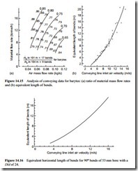
To show the difference between the two sets of data in Figure 14.4 the ratio of the mass flow rates is presented in Figure 14.15a. A grid was constructed on Figure 14.14a of constant pressure drop, spaced at 0.4 bar, and constant air flow rate, spaced at 0.01 kg/s. The values plotted represent the ratio of the mass flow rate of barytes in the pipeline
with 17 bends to that of the mass flow rate of barytes in the pipeline with nine bends. The slope of the lines drawn, of constant value of the ratio through the data, is very similar to those of constant conveying air velocity. With the ratio decreasing from about 0.85 at low velocity to 0.65 at high velocity the influence of the bends, and also that of velocity, clearly have a very significant influence on the conveying capability of pipelines [3].
In order to assign a value of equivalent length to the bends Equation (14.3) can be used for this purpose:
With the mass flow rate ratios plotted on Figure 14.15a, Equation (14.9) can be solved for every grid point. This was done and a number of correlations were tried but the only one that produced a consistent relationship was in terms of conveying line inlet air velocity. This is presented in Figure 14.15b. A very similar relationship was derived for the cement and a mean of the two sets of data is presented in Figure 14.16. This shows that for low velocity, dense phase conveying, the equivalent length of bends is very low, being only about 2 m per bend at 4 m/s, but rises considerably for dilute phase suspension flow, being about 16 m per bend at 15 m/s [3].
Bend location
This method of analysis is very straightforward and can be undertaken with little in the way of instrumentation. One problem that it cannot solve, however, is that of whether the location of the bend in the pipeline is important. The correlation presented in Figure 14.14b is in terms of the conveying line inlet air velocity and it was not pos- sible to detect any influence of position along the length of the pipeline.
The test work was undertaken with single bore pipelines and so the velocity will increase from one bend to the next. Conveying line pressure drops of up to 4 bar were employed and so in some tests there will have been a fivefold increase in velocity from the start to the end of the pipeline. It might be expected that the pressure drop across a bend would depend to a large extent on the velocity at the bend itself. Pressure drop, however, is due to re-acceleration of the particles, as discussed in Section 5.2.4.3 and so it is the difference in velocity across the bend that is probably more important.
Pressure drop data
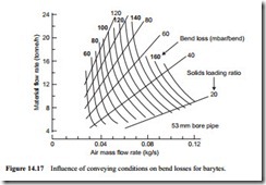
An alternative form of this data for the barytes, but derived in the form of actual values of pressure drop was presented in Figure 11.16 and this is reproduced here in Figure
14.17 for comparison. This data does not identify bend location either and assumes that the pressure drop for each bend in the pipeline is the same. A similar wide range of values, from 50 mbar/bend for dense phase to 170 mbar/bend for dilute phase con- veying were obtained. The significance of this is that if there are six bends in a pipeline and the pressure loss is 170 mbar/bend, then a pressure drop of one bar is attributed simply to the convenience of pipeline routing. The necessity of each bend in a pipeline, therefore, should be given serious consideration.
Classical analysis
The classical method of determining the pressure drop across a bend in a pipeline is to use pressure transducers along the length of the pipeline as discussed in Section 5.2.4.3.
Typical of the method employed, analysis and data obtained are the results presented in Figure 14.18 [1]. The material conveyed here was a wheat flour, conveyed at a solids loading ratio of about thirty in a 53 mm bore pipeline. The bend had a D/d ratio of about 5:1. The pressure profile indicated by the data points clearly shows the pressure drop due to the re-acceleration of the particles that occurs in the straight length of pipeline following the bend. The pressure drop attributed to the bend is determined as indicated in Figure 14.18.
With pressure transducers in the straight length of pipeline approaching the bend it is possible to determine the pressure gradient in this section of pipeline. With this recorded at about 5.6 mbar/bend, and the pressure drop across the bend assessed at about 130 mbar, the equivalent length of the bend comes to approximately 23 m. The conveying line inlet air velocity to the pipeline was about 16 m/s and so although the data point appears to fit well on Figure 14.17, the equivalent length is very much greater than that predicted in Figure 14.16.
It is believed that the increase in equivalent length, and hence pressure drop, is due to the material. It has already been shown that the conveying characteristics for differ- ent materials can vary significantly. This has been for the total pipeline and so a major element of this difference may well be due to the bends. From Figure 14.18 it will be seen that much of the energy loss is due to re-accelerating the particles after leaving the bend. The coefficient of restitution between the particles and the bend walls must play a part. Cement and barytes are relatively hard materials, while flour is very much softer. The flour, therefore, will probably have a lower coefficient of restitution and hence have a lower exit velocity from bends, which will result in a higher pressure drop. This aspect of pipeline performance is considered further when pipeline material is considered later in this chapter.
Bend geometry
The bends for which the data was presented in Figures 14.16 and 14.17 had a bend diameter to pipe bore ratio of 24:1. Bends having a wide range of geometries, however, are employed in conveying system pipelines, as illustrated earlier in Figure 5.1. Short radius bends and elbows are cheaper to install than long radius bends, take up less space and are easier to support. To combat erosive wear, however, long radius bends are often employed.
Figure 14.16 shows that the equivalent resistance for each bend varies from about 2 m in low velocity, dense phase conveying, to more than 20 m in high velocity, dilute phase flow. In the scaling procedure for conveying distance the model presented in Equation (14.4) has been found to work well for pipeline combinations of both distance and bends, if the total equivalent length of the pipeline is used.
Air only relationships
The influence of bend geometry on pressure drop with air only has been well documented. Representative data was presented in Figure 10.6 and is reproduced for refer- ence in Figure 14.19a. This would tend to indicate that for radiused bends there is little influence of bend geometry on pressure loss for a very wide range of D/d ratios. It is only with very short radius bends, below a D/d ratio of about 3:1, that there is any sig- nificant change. Below this value pressure prop would appear to increase considerably. Modelling procedures for single phase flow for bends was considered with Equation (10.8), and in terms of an equivalent length with Equation (10.9).
Conveying data
In order to assess the relative effects of bend geometry on pressure drop, a pipeline was specially built with a double loop in which the bends at the corners could be easily
replaced [2]. The pipeline was about 50 m long, of 53 mm bore and contained a total of eleven 90° bends.
Seven of the bends were changed at a time and tests were carried out with sets of long radius bends, (D/d = 24), short radius bends (D/d = 6), elbows (D/d = 2) and blind tees (D/d = 0). A proportioned sketch of the bends is given in Figure 14.19b and a sketch of the pipeline employed is given in Figure 14.20. Fine fly ash was used as the conveyed material so that a very wide range of conveying conditions could be examined.
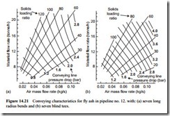
A full set of conveying characteristics was obtained for each of the four sets of bends tested in this common pipeline. Two of the sets of conveying characteristics obtained are shown in Figure 14.21. They are for the pipeline with seven long radius bends, which are presented in Figure 14.21a, and for the pipeline with seven blind tees, which are shown in Figure 14.21b.
It will be seen from these conveying characteristics that the tests were carried out over a very wide range of conveying conditions, with solids loading ratios up to 120 and conveying line inlet air velocities down to about 4 m/s. The fly ash was conveyed over a similar wide range of conveying conditions with each of the other two sets of bends tested. With four sets of conveying characteristics, for the same material conveyed through the same pipeline, it was possible to analyse the relative influence of the different bend sets tested [4].
A characteristic of fine fly ash, from previous conveying data, has been the very steep slope of the constant pressure drop lines, and this will be observed in both sets of data included in Figure 14.21. Although the only difference between the two sets of conveying data in Figure 14.21 is the change in geometry of seven of the bends, the difference in conveying performance is quite dramatic.
Comparison of performance
To illustrate the difference: if a pressure drop of 1.8 bar and an air flow rate of 0.05 kg/s are considered it will be seen that 10 tonne/h of fly ash will be conveyed through the pipeline with the seven blind tees, and 20 tonne/h will be achieved through the same pipeline with seven long radius bends. This is a 100 per cent improvement in
performance for no change in power input, no change in conveying distance, and only seven of the eleven bends in the pipeline changed.
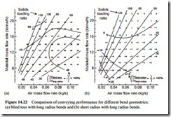
To provide a global comparison between the sets of data, rectangular grids were drawn on the sets of conveying characteristics and the pressure drop noted for every grid point. The comparison was based on the pressure drop required to achieve a specified material flow rate for a given air flow rate. This comparison was undertaken over the entire range of conveying conditions.
A comparison of the blind tees and long radius bends is given in Figure 14.22a. It will be seen from this that the pressure drop in the line with the blind tees was about 40 per cent greater than that for the line with the long radius bends. This increase in pressure drop is due entirely to the additional resistance created by changing seven long radius bends for blind tees, since everything else associated with the two pipelines is common. In terms of energy considerations, therefore, blind tees could not be recom- mended for conveying system lines [4].
A similar comparison for the elbows (D/d = 2) and long radius bends showed that when the conveying line pressure drop was below about 1.2 bar the elbows were slightly better than the long radius bends, with a maximum improvement of about 10 per cent. Above 1.2 bar the situation was revered and the conveying line pressure drop for the elbows was up to about 20 per cent greater.
A comparison of the short radius (D/d = 6) and long radius bends is given in Figure 14.22b. This shows that the short radius bends are clearly the best of those tested in terms of minimum pressure drop. Only at the very highest material flow rates are the long radius bends slightly better.
It must be realized that the pressure drop ratios given in the data presented in Figure 14.22 are for the total pipeline system and not just the set of seven bends.
The pressure drop for the horizontal pipeline and the connecting bends will be approximately constant, and so the pressure drop ratios for the seven bends alone will be significantly higher. In terms of bends alone, therefore, the data presented for air alone in Figure 14.19a appears to hold reasonably well for the conveying of material also.
