Wobble Plate Inline Pumps
A variation of the inline piston design is the wobble plate pump. In a wobble plate design, the cylinder is stationary and the canted plate is turned by the drive shaft.As the plate turns, it wobbles and pushes against spring-loaded pistons to force them to reciprocate. Separate inlet and outlet check valves are required because the cylinders do not move past the ports .
Bent Axis Pumps
In a bent axis piston pump (Figure 3-18), the cylinder block turns with the drive shaft, but at an offset angle. The piston rods are attached to the drive shaft flange by ball
joints and are forced in and out of their bores as the distance between the drive shaft flange and cylinder block changes (Figure 3-19). A universal link keys the cylinder block to the drive shaft to maintain alignment and ensure that they turn together. Except to accelerate and decelerate the cylinder block and to overcome resistance of the oil-filled housing, the link does not transmit force.
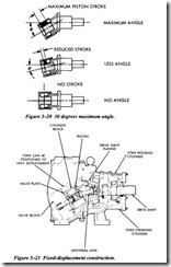
The displacement of this type of pump varies with the offset angle (Figure 3-20), the maxi mum angle being 30 degrees and the minimum zero. Fixed-displacement models (Figure 3-21) are usually available with 23-degree or 30-degree angles. In the variable-displacement construction (Figure 3-22), a yoke with an external control is used to change the angle. With some controls, the yoke can be moved over center to reverse the direction of flow.
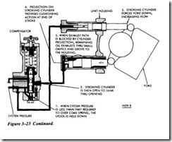
Various methods are used to control the displacement of bent-axis pumps. Typical controls are the handwheel, pressure compensator and servo. Figure 3-23 shows a pressure compensator control for a bent-axis pump. In view A, the system pressure is
sufficient to overcome the spring force of the compensator. As a result, the spool lifts, allowing fluid to flow into the stroking cylinder. Although the holding cylinder also has system pressure applied, the area of the stroking cylinder piston is much greater. Because of the differential pressure, the yoke is forced up to decrease flow. View B shows the yoke moving down as system pressure drops below that required to over come the compensator spring force.


