■ AIR-CONDITIONING PROCESSES
Maintaining a living space or an industrial facility at the desired temperature and humidity requires some processes called air-conditioning processes. These processes include simple heating (raising the temperature), simple cooling (lowering the temperature), humidifying (adding moisture), and dehumidifying (removing moisture). Sometimes two or more of these processes are needed to bring the air to a desired temperature and humidity level.
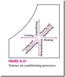
Various air-conditioning processes are illustrated on the psychrometric chart in Fig. 9–31. Notice that simple heating and cooling processes appear as horizontal lines on this chart since the moisture content of the air remains constant (v = constant) during these processes. Air is commonly heated and humidified in winter and cooled and dehumidified in summer. Notice how these processes appear on the psychrometric chart.
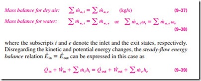
Most air-conditioning processes can be modeled as steady-flow processes, and thus the mass balance relation m· in = m· out can be expressed for dry air and water as
The work term usually consists of the fan work input, which is small relative to the other terms in the energy balance relation. Next we examine some commonly encountered processes in air-conditioning.
Simple Heating and Cooling (V = constant)
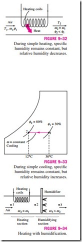
Many residential heating systems consist of a stove, a heat pump, or an electric resistance heater. The air in these systems is heated by circulating it through a duct that contains the tubing for the hot gases or the electric resistance wires, as shown in Fig. 9–32. The amount of moisture in the air remains constant during this process since no moisture is added to or removed from the air. That is, the specific humidity of the air remains constant (v = constant) during a heating (or cooling) process with no humidification or dehumidification. Such a heating process will proceed in the direction of increasing dry-bulb temperature following a line of constant specific humidity on the psychrometric chart, which appears as a horizontal line.
Notice that the relative humidity of air decreases during a heating process even if the specific humidity v remains constant. This is because the relative humidity is the ratio of the moisture content to the moisture capacity of air at the same temperature, and moisture capacity increases with temperature. Therefore, the relative humidity of heated air may be well below comfortable levels, causing dry skin, respiratory difficulties, and an increase in static electricity.
A cooling process at constant specific humidity is similar to the heating process discussed above, except the dry-bulb temperature decreases and the relative humidity increases during such a process, as shown in Fig. 9–33. Cooling can be accomplished by passing the air over some coils through which a refrigerant or chilled water flows.
The conservation of mass equations for a heating or cooling process that involves no humidification or dehumidification reduce to dry air and v1 = v2 for water. Neglecting any fan work that may be present, the conservation of energy equation in this case reduces to
where h1 and h2 are enthalpies per unit mass of dry air at the inlet and the exit of the heating or cooling section, respectively.
Heating with Humidification
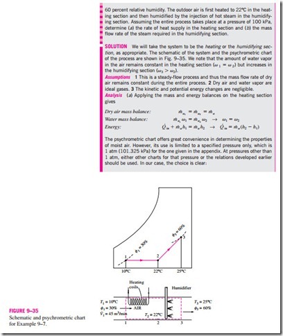
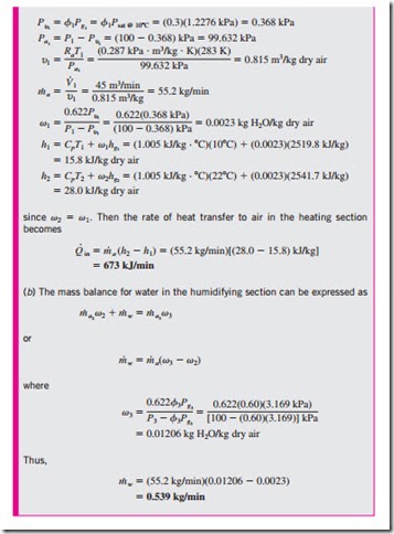
Problems associated with the low relative humidity resulting from simple heating can be eliminated by humidifying the heated air. This is accomplished by passing the air first through a heating section (process 1-2) and then through a humidifying section (process 2-3), as shown in Fig. 9–34.
The location of state 3 depends on how the humidification is accomplished. If steam is introduced in the humidification section, this will result in humidification with additional heating (T3 > T2). If humidification is accomplished by spraying water into the airstream instead, part of the latent heat of vaporization will come from the air, which will result in the cooling of the heated airstream (T3 < T2). Air should be heated to a higher temperature in the heating section in this case to make up for the cooling effect during the humidification process.
Cooling with Dehumidification
The specific humidity of air remains constant during a simple cooling process, but its relative humidity increases. If the relative humidity reaches un- desirably high levels, it may be necessary to remove some moisture from the air, that is, to dehumidify it. This requires cooling the air below its dew-point temperature.
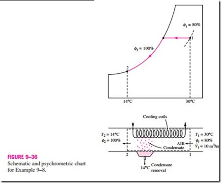
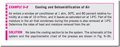
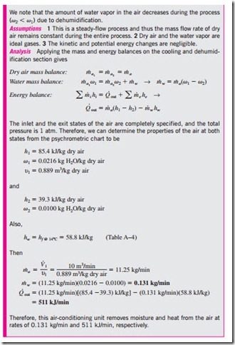
The cooling process with dehumidifying is illustrated schematically and on the psychrometric chart in Fig. 9–36 in conjunction with Example 9–8. Hot, moist air enters the cooling section at state 1. As it passes through the cooling coils, its temperature decreases and its relative humidity increases at
constant specific humidity. If the cooling section is sufficiently long, air will reach its dew point (state 2, saturated air). Further cooling of air results in the condensation of part of the moisture in the air. Air remains saturated during the entire condensation process, which follows a line of 100 percent relative humidity until the final state (state 3) is reached. The water vapor that condenses out of the air during this process is removed from the cooling section through a separate channel. The condensate is usually assumed to leave the cooling section at T3.
The cool, saturated air at state 3 is usually routed directly to the room, where it mixes with the room air. In some cases, however, the air at state 3 may be at the right specific humidity but at a very low temperature. In such cases, air is passed through a heating section where its temperature is raised to a more comfortable level before it is routed to the room.
Evaporative Cooling
Conventional cooling systems operate on a refrigeration cycle, and they can be used in any part of the world. But they have a high initial and operating cost. In desert (hot and dry) climates, we can avoid the high cost of cooling by using evaporative coolers, also known as swamp coolers.
Evaporative cooling is based on a simple principle: As water evaporates, the latent heat of vaporization is absorbed from the water body and the surrounding air. As a result, both the water and the air are cooled during the process.
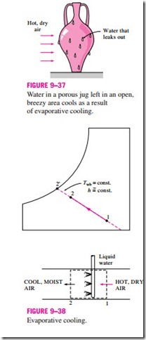
This approach has been used for thousands of years to cool water. A porous jug or pitcher filled with water is left in an open, shaded area. A small amount of water leaks out through the porous holes, and the pitcher “sweats.” In a dry environment, this water evaporates and cools the remaining water in the pitcher (Fig. 9–37).
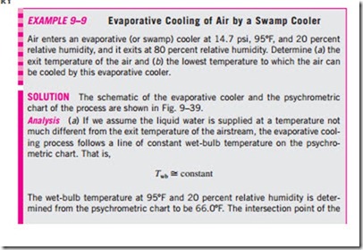
You have probably noticed that on a hot, dry day the air feels a lot cooler when the yard is watered. This is because water absorbs heat from the air as it evaporates. An evaporative cooler works on the same principle. The evaporative cooling process is shown schematically and on a psychrometric chart in Fig. 9–38. Hot, dry air at state 1 enters the evaporative cooler, where it is sprayed with liquid water. Part of the water evaporates during this process by absorbing heat from the airstream. As a result, the temperature of the airstream decreases and its humidity increases (state 2). In the limiting case, the air will leave the evaporative cooler saturated at state 2′. This is the lowest temperature that can be achieved by this process.
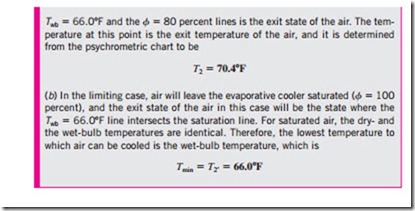
The evaporative cooling process is essentially identical to the adiabatic saturation process since the heat transfer between the airstream and the surroundings is usually negligible. Therefore, the evaporative cooling process follows a line of constant wet-bulb temperature on the psychrometric chart. (Note that this will not exactly be the case if the liquid water is supplied at a temperature different from the exit temperature of the airstream.) Since the constant-wet-bulb-temperature lines almost coincide with the constant- enthalpy lines, the enthalpy of the airstream can also be assumed to remain constant. That is,
Adiabatic Mixing of Airstreams
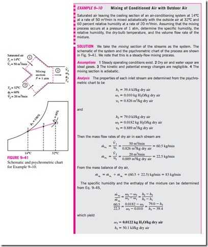
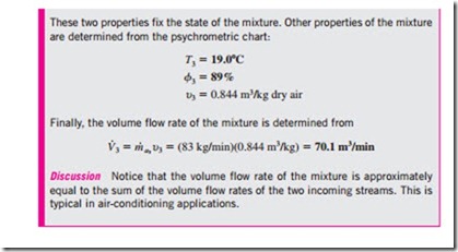
Many air-conditioning applications require the mixing of two airstreams. This is particularly true for large buildings, most production and process plants, and hospitals, which require that the conditioned air be mixed with a certain fraction of fresh outside air before it is routed into the living space. The mixing is accomplished by simply merging the two airstreams, as shown in Fig. 9–40.
The heat transfer with the surroundings is usually small, and thus the mixing processes can be assumed to be adiabatic. Mixing processes normally involve no work interactions, and the changes in kinetic and potential energies, if any, are negligible. Then the mass and energy balances for the adiabatic mixing of two airstreams reduce to
This equation has an instructive geometric interpretation on the psychrometric chart. It shows that the ratio of v2 – v3 to v3 – v1 is equal to the dashed line AB. The ratio of h2 – h3 to h3 – h1 is also equal to the ratio of to m· a , and the states that satisfy this condition are indicated by the dashed line CD. The only state that satisfies both conditions is the intersection point of these two dashed lines, which is located on the straight line connecting states 1 and 2. Thus we conclude that when two airstreams at two different states (states 1 and 2) are mixed adiabatically, the state of the mixture (state 3) will lie on the straight line connecting states 1 and 2 on the psychrometric chart, and the ratio of the distances 2-3 and 3-1 is equal to the ratio of mass flow rates The concave nature of the saturation curve and the conclusion above lead to an interesting possibility. When states 1 and 2 are located close to the saturation curve, the straight line connecting the two states will cross the saturation are mixed adiabatically, the state of the mixture lies on the straight line connecting the two states.
curve, and state 3 may lie to the left of the saturation curve. In this case, some water will inevitably condense during the mixing process.
Wet Cooling Towers
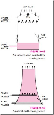
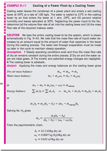
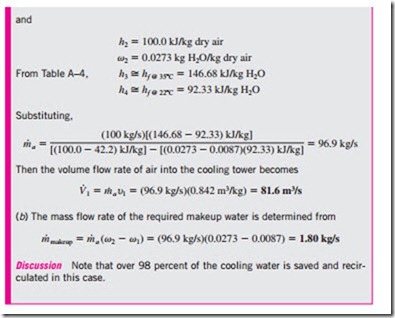
Power plants, large air-conditioning systems, and some industries generate large quantities of waste heat that is often rejected to cooling water from nearby lakes or rivers. In some cases, however, the water supply is limited or thermal pollution is a serious concern. In such cases, the waste heat must be rejected to the atmosphere, with cooling water recirculating and serving as a transport medium for heat transfer between the source and the sink (the atmosphere). One way of achieving this is through the use of wet cooling towers. A wet cooling tower is essentially a semienclosed evaporative cooler. An induced-draft counterflow wet cooling tower is shown schematically in Fig. 9–42. Air is drawn into the tower from the bottom and leaves through the top. Warm water from the condenser is pumped to the top of the tower and is sprayed into this airstream. The purpose of spraying is to expose a large surface area of water to the air. As the water droplets fall under the influence of gravity, a small fraction of water (usually a few percent) evaporates and cools the remaining water. The temperature and the moisture content of the air increase during this process. The cooled water collects at the bottom of the tower and is pumped back to the condenser to pick up additional waste heat. Makeup water must be added to the cycle to replace the water lost by evaporation and air draft. To minimize water carried away by the air, drift eliminators are installed in the wet cooling towers above the spray section.
The air circulation in the cooling tower just described is provided by a fan, and therefore it is classified as a forced-draft cooling tower. Another popular type of cooling tower is the natural-draft cooling tower, which looks like a large chimney and works like an ordinary chimney. The air in the tower has a high water-vapor content, and thus it is lighter than the outside air. Consequently, the light air in the tower rises, and the heavier outside air fills the vacant space, creating an airflow from the bottom of the tower to the top. The flow rate of air is controlled by the conditions of the atmospheric air. Natural- draft cooling towers do not require any external power to induce the air, but they cost a lot more to build than forced-draft cooling towers. The natural- draft cooling towers are hyperbolic in profile, as shown in Fig. 9–43, and some are over 100 m high. The hyperbolic profile is for greater structural strength, not for any thermodynamic reason.
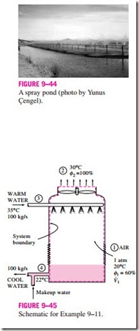
The idea of a cooling tower started with the spray pond, where the warm water is sprayed into the air and is cooled by the air as it falls into the pond, as shown in Fig. 9–44. Some spray ponds are still in use today. However, they re- quire 25 to 50 times the area of a cooling tower, water loss due to air drift is high, and they are unprotected against dust and dirt.
We could also dump the waste heat into a still cooling pond, which is basically a large artificial lake open to the atmosphere. Heat transfer from the pond surface to the atmosphere is very slow, however, and we would need about 20 times the area of a spray pond in this case to achieve the same cooling.
