Power drive systems
In all types of rotating machinery, the use of a VFD frees the designer from the traditional constraints of designing machinery for the specific rotational speeds detailed in Table 6.1, and even allows operation at higher speed. In many instances, pump designers have to develop products to be sold in markets with both 50 Hz and 60 Hz base frequencies and best efficiency may be achieved at some point between these levels. Particularly with centrifugal equipment such as fans or pumps, VSDs allow machinery to be operated closer to optimum specific speed for a much wider range of duties.
Traditionally VFDs have often been applied to existing and new motor systems as a stand alone component, placed between the power network and the motor. As the VFD market is maturing the number of products continues to increase. Packaging of motors and drives, as well as the concept of integrated solutions and integrated motorNFD units, are now readily available as alternatives to purchasing stand-alone drives.
When a stand-alone drive is applied, it is important to ascertain that it is compatible with the motor, the motor cabling and the power network system. Drive motor systems available from system integrators, as well as packaged systems generally assure that the selected components will work well together. The integrated motorNFD unit, described in more detail below, represents a virtual guarantee for full compatibility between drive and motor.
Integrated motors and drives
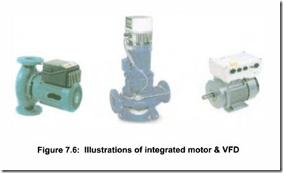
A number of motor and drive manufacturers are now producing integrated motorNFD units (see examples in Figure 7.6). These units consist of a motor and a specially designed VFD, produced as a single package, with the VFD unit mounted variously on the top, side, or end of the motor. Currently these designs are available up to approximately 22 kW (30 hp).
Integrated motors and drives can feature a number of advantages:
• Motor and VFD are properly matched
• Installed costs can be less than that of a separate motor and VFD
• No special cables between VFD and motor, saving installation time and screened cables
• Reduced over-voltage on the motor windings due to the short length of the connections, leading to a longer life of the insulation
• No output cables. Hence radiated emissions are minimized
• VFD shares motor cooling system
• Better compatibility between all the components of the drive system, reduces noise & vibration
• Often easier and faster to retrofit in a building or industrial
