Fluid flow
Hydraulic and pneumatic systems are both concerned with the flow of a fluid (liquid or gas) down a pipe. Flow is a loose term that generally has three distinct meanings:
• volumetric flow is used to measure volume of fluid passing a point per unit of time. Where the fluid is a compressible gas, temperature and pressure must be specified or flow normalised to
some standard temperature and pressure (a topic discussed later). Volumetric flow is the most common measurement in process control
• mass flow measures the mass of fluid passing the point in unit time
• velocity of flow measures linear speed (in m s-1, say) past the point of measurement. Flow velocity is of prime importance in the design of hydraulic and pneumatic systems.
Types of fluid flow are illustrated in Figure 1.16. At low flow velocities, the flow pattern is smooth and linear with low velocities at the pipe walls and the highest flow at the centre of the pipe. This is known as laminar or streamline flow.
As flow velocity increases, eddies start to form until at high flow velocities complete turbulence results as shown in Figure 1.16b. Flow velocity is now virtually uniform across the pipe.
The nature of the flow is determined by the Reynolds number, Rc, given by the expression:
where v is flow velocity, d is pipe diameter, p the fluid density and ‘YJ the viscosity. The Reynolds number is a ratio and hence dimen sionless. If Rc < 2000, flow is laminar. If Rc > I 05, flow is turbulent.
A turbulent flow is generally preferred for products in process control as it simplifies volumetric flow measurement (with differ ential pressure flowmeters – see later). Turbulent flow, however, increases energy loss through friction and may lead to premature wear. Cavitation (formation and collapse of vapour bubbles) occurs with turbulent liquid flow and may result in pitting on valve sur faces. Laminar flow is therefore specified for hydraulic and pneu matic systems. This results in a desired flow velocity of about 5 m s-2.
Energy in a unit mass of fluid has three components:
• kinetic energy from its motion, given by v2/2 where v is flow velocity
• potential energy from the height of the fluid
• energy arising from the pressure of the fluid, given by PIp where P is the pressure and p the density.
Fluid is passing along a pipe in Figure 1.17. Neglecting energy losses from friction, energies at points X, Y and Z will be equal. The flow velocity at point Y, however, is higher than at points X and Z
because of the smaller pipe diameter. Potential energy at each point is constant because the pipe is horizontal. so we can write:
We have implied an incompressible fluid by assuming the density, p, is constant throughout. Expression 1.13 becomes more compli cated for a gas as different densities have to be used at each point.
The net result of the expression is fluid pressure falls as flow velocity rises. Note, though, that the pressure recovers as flow velocity falls again at point Z.
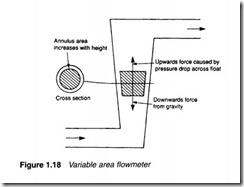
The simplest method of measuring flow (known as a variable area flowmeter) uses a float in a vertical tube arranged as Figure 1.18. The obstruction of the float causes a local increase in the fluid velocity which causes a differential pressure drop across the float, resulting in an upward force. The weight of the float obviously causes a downward force. The float therefore rises or falls depending on which force is the largest. The area around the float, however, increases the higher the float rises because of the tube taper. This increase in area decreases the pressure drop across the float and the upwards force. The float therefore settles at a vertical
position where the weight of the float and the upwards force from the differential pressure exactly match. Flow rate can therefore be determined from the float position.
A remote indicating flowmeter can be constructed from a pipe mounted turbine, as shown in Figure 1.19. Fluid flow causes the propeller to rotate, its rotational speed being proportional to flow rate. Blade rotation is counted electronically by an external inductive proximity detector to give an electrical signal for remote indication of the flow rate.
Finally, the classical method of measuring flow returns directly to expression 1.13 by locally increasing flow velocity with a deliberately introduced restriction as shown in Figure 1.20. Typical obstructions are an orifice plate or a venturi. These increase flow velocity, causing a pressure drop which can be measured to give a differential pressure related to the flow. Unfortunately, the differential pressure is proportional to the square of the flow rate, so a linearising square root extractor circuit is required to give a linear signal. Although differential pressure flow measurement is widely used to measure the flow rates of process material, the technique is not widely used in hydraulic and pneumatic systems.
It will be apparent that all flow measurement systems are intrusive to various degrees, and cannot be tapped in as easily as pressure measurement can. Fault finding in hydraulic and pneumatic systems is therefore generally based on pressure readings at strategic points.


