Pressure-controlled sequences
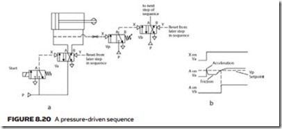
Many simple applications can be controlled without limit switches by using the pressure rise when a cylinder reaches end of stroke to operate a shuttle valve. In Figure 8.20 a pulse on the solenoid valve shifts valve Va, causing cylinder A
to extend. There is no load on the cylinder so the extend pressure is low. When the cylinder reaches the end of the stroke (or the load is gripped), the pressure will rise as shown. This rise in pressure shifts valve Vb for the next step in the sequence.
modular sequence valves
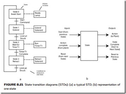
Most sequences can be considered to be a series of states. Each state causes one or more actions and the sequence progresses from state to state as signals from limit switches and similar devices occur. The sequence can be represented by a diagram such as Figure 8.21a, which is known as a state transition diagram, or STD, which shows the states, the actions performed in each state and the input signals which step the sequence from one state to the next state. For example, a state could extend a cylinder and the step onto the next state could be made by the cylinder extended limit.
A state can thus be represented by Figure 8.21b. It has three inputs: start, action(s) complete and reset (the last signal coming from the succeeding state); and three outputs: action (to the actuator(s)), state complete (to start on the next state) and reset (to the previous state).
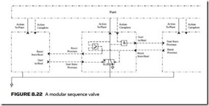
Modular sequence valves provide the features needed to provide one state of an STD. Each state has one valve which is a single unit pre-made as in Figure 8.22 with a shuttle valve, an AND gate and an OR gate. The start command (from the completion of the previous state) shifts the shuttle valve and provides the action signal to the actuator(s). This signal also goes via the OR gate to reset the previous state. When the actuator has completed its action the action complete
signal from the plant AND the action signal give the complete signal which acts as the start signal for the next valve. The reset signal from the next valve shifts the first shuttle valve back, removing the signal to the actuator(s) ready for the next sequence.
The action output signal can be combined with other action outputs from other states by AND and OR gates in cases where an identical action is required in more than one state.


