ROTARY COMPRESSORS
The rotary compressor is adaptable to direct drive by induction motors or multicylinder gasoline or diesel engines. The units are compact and relatively inexpensive, and require a minimum of operating attention and maintenance. They occupy a fraction of the space and weight of a reciprocating machine of equivalent capacity. Rotary compressor units are classified into three general groups: sliding-vane type, lobe type, and liquid seal ring type.
Sliding-Vane Compressors
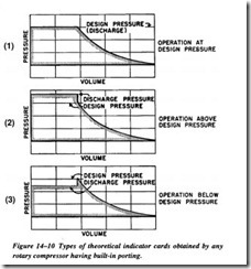
The rotary sliding-vane compressor has as its basic element the cylindrical casing with its heads and rotor assembly. When running at design pressure, the theoretical indicator card is identical to a reciprocating compressor. There is one major difference between a sliding-vane and a reciprocating compressor. The reciprocating unit has spring-loaded valves that open automatically on small pressure differentials between the outside and inside cylinder. The discharge valve, therefore, opens as soon as point 2 (Figure 14-10) is reached and the inlet as point 4 is reached , even though there may be some variation in the discharge pressure.
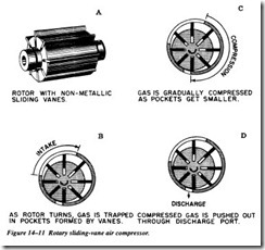
The sliding-vane compressor has no valves . The times in the cycle when the inlet and discharge open are determined by the location of ports over which the vanes pass. The inlet porting is normally wide and is designed to admit gas up to the point when the pocket between two vanes is the largest. It is closed when the following vane of each pocket passes the edge of the inlet port .
The pocket volume decreases as the rotor turns and the gas is compressed. Compression continues until the leading vane of each pocket uncovers the discharge port. This point must be preset, or built in when the unit is manufactured. Thus, the compressor
always compresses the gas to design pressure, regardless of the pressure in the receiver tank.
The rotary sliding-vane type, as illustrated in Figure 14-11, has longitudinal vanes, sliding radially in a slotted rotor mounted eccentrically in a cylinder. The centrifugal force carries the sliding vanes against the cylindrical case with the vanes forming a number of individual longitudinal cells in the eccentric annulus between the case and rotor. The suction port is located where the longitudinal cells are largest. The size of each cell is reduced by the eccentricity of the rotor as the vanes approach the dis charge port, thus compressing the vapor.
Design Fundamentals
The fundamental design considerations of a sliding-vane compressor include the following:
Cylinder. Cast iron is the standard material, but other materials may be used if corrosive conditions exist. The heads contain the bearings and necessary shaft seals. On most standard air compressors, the shaft seals are semirnetallic packing in a stuffing box. Commercial mechanical rotary
seals can be supplied where necessary or desired. Cylindrical roller bear ings are standard.
The rotor is usually one piece with the steel shaft using either bar stock or a special forging. Occasionally, the rotor may be a separate iron casting, keyed to the shaft. Vanes are usually asbestos or cotton cloth, impregnated with a phenolic resin. Bronze or aluminum may also be used for vane construction. Each vane fits into a milled slot extending the full length of the rotor and slides radially in and out of this slot once per revolution. Vanes are the most maintenance-prone part in the compressor. There are from 8 to 20 vanes in each rotor, depending on diameter. The greater number of vanes increases compartmentalization and reduces the pressure differential across each vane.
Lubrication. A V-belt-driven force-feed lubricator is used on water-cooled compressors. Oil goes to both bearings and to several points in the cylin der. Ten times as much oil is recommended to lubricate the rotary cylinder as is required for the air cylinder of a corresponding reciprocating com pressor. The oil carried over with the gas to the line may be reduced 50 percent with an oil separator on the discharge. Use of an aftercooler ahead of the separator permits removal of 85 to 90 percent of the entrained oil.
Failure Modes
A sliding-vane compressor has failure modes common to vane-type pumps. The dominant vibration profile components will include running speed, vane-pass frequency, and bearing rotational frequencies. In normal operation, all of these frequency com ponents will be low level, with the dominant energy at running speed of the shaft.
Analysis of sliding-vane compressors will use the same techniques and methods as that of any rotating machine train. Load, speed, and process variables must be consid ered. Common failures of this type of compressor include the following:
Shaft seals. Leakage through the shaft seals should be checked visually once a week or as part of every data acquisition route. Leakage may not extend to the outside of the gland, and if taken off in a vent, the vent discharge should be arranged for easy inspection. Leakage beyond normal is the signal for replacement. Under good conditions, seals have a normal life of 10,000 to 15,000 hours and should be replaced when this service life has been reached.
Vanes. Vanes wear continuously on their outer edges and, to some degree, on the faces that slide in and out of the slots. The vane material is affected somewhat by prolonged heat and gradually deteriorates. Typical life, in 100-psig service, is about 16,000 hours of operation and on low-pressure applications may reach 32,000 hours.
Vane replacement before breakage is extremely important. Breakage while operating can severely damage the compressor and usually forces a complete overhaul and realignment of heads and clearances.
Bearings. In normal service, bearings have a relatively long life, but replacement after about 6 years of operation is recommended. Bearing defects will be dis played in the same manner as any rotating machine train. Inner and outer race defects will be the dominant failure mode, but roller spin may also be present.

