THE IDEAL REHEAT RANKINE CYCLE
We noted in Section 8–12 that increasing the boiler pressure increases the thermal efficiency of the Rankine cycle, but it also increases the moisture con- tent of the steam to unacceptable levels. Then it is natural to ask this question:
How can we take advantage of the increased efficiencies at higher boiler pressures without facing the problem of excessive moisture at the final stages of the turbine?
Two possibilities come to mind:
1. Superheat the steam to very high temperatures before it enters the turbine. This would be the desirable solution since the average temperature at which heat is added would also increase, thus increasing the cycle efficiency. This is not a viable solution, however, since it will require raising the steam temperature to metallurgically unsafe levels.
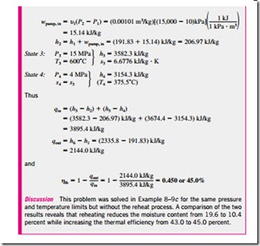
2. Expand the steam in the turbine in two stages, and reheat it in between. In other words, modify the simple ideal Rankine cycle with a reheat process. Reheating is a practical solution to the excessive moisture problem in tur- bines, and it is commonly used in modern steam power plants.
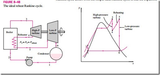
The T–s diagram of the ideal reheat Rankine cycle and the schematic of the power plant operating on this cycle are shown in Fig. 8–48. The ideal reheat Rankine cycle differs from the simple ideal Rankine cycle in that the expansion
process takes place in two stages. In the first stage (the high-pressure turbine), steam is expanded isentropically to an intermediate pressure and sent back to the boiler where it is reheated at constant pressure, usually to the inlet temperature of the first turbine stage. Steam then expands isentropically in the second stage (low-pressure turbine) to the condenser pressure. Thus the total heat in- put and the total turbine work output for a reheat cycle become
The incorporation of the single reheat in a modern power plant improves the cycle efficiency by 4 to 5 percent by increasing the average temperature at which heat is added to the steam.
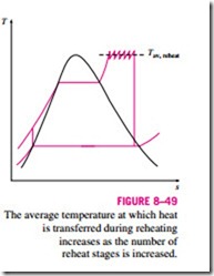
The average temperature during the reheat process can be increased by in- creasing the number of expansion and reheat stages. As the number of stages is increased, the expansion and reheat processes approach an isothermal process at the maximum temperature, as shown in Fig. 8–49. The use of more T than two reheat stages, however, is not practical. The theoretical improvement in efficiency from the second reheat is about half of that which results from a single reheat. If the turbine inlet pressure is not high enough, double reheat would result in superheated exhaust. This is undesirable as it would cause the average temperature for heat rejection to increase and thus the cycle efficiency to decrease. Therefore, double reheat is used only on supercritical-pressure (P > 22.09 MPa) power plants. A third reheat stage would increase the cycle efficiency by about half of the improvement attained by the second reheat. This gain is too small to justify the added cost and complexity.
The reheat cycle was introduced in the mid-1920s, but it was abandoned in the 1930s because of the operational difficulties. The steady increase in boiler pressures over the years made it necessary to reintroduce single reheat in the late 1940s and double reheat in the early 1950s.
The reheat temperatures are very close or equal to the turbine inlet temper- ature. The optimum reheat pressure is about one-fourth of the maximum cycle pressure. For example, the optimum reheat pressure for a cycle with a boiler pressure of 12 MPa is about 3 MPa.
Remember that the sole purpose of the reheat cycle is to reduce the moisture content of the steam at the final stages of the expansion process. If we had materials that could withstand sufficiently high temperatures, there would be no need for the reheat cycle.
Incoming search terms:
- Reheat Rankine cycle
- rankine cycle with Reheat
- the ideal reheat rankine cycle
- https://yandex ru/clck/jsredir?from=yandex ru;search;web;;&text=&etext=1828 yUWmMZcOA22W37gfpijTF3i30vcteA9slxg0k7o3B0vEXvG3h8NgKqZFk0NE5fIR5bQePXr51iVQMI2-HAm0Ng 5dc3f16c591d97d0f0e1fed6c92f583e5ba24d36&uuid=&state=_BLhILn4SxNIvvL0W45KSic
- ideal reheat Rankine cycle
- modified rankine cycle thermal power plant
- rankine cycle in refrigerator
- re-heat cycle
- reheat rankin cycle
