Pressure gauges and indicators
The SI unit of pressure is the pascal (Pa), which is the special name given to the newton/ m2 (N/m2). The pascal is only suitable for small pressures so kilopascal (kPa) and megapascal (MPa) are preferred for higher pressures. The practical unit for pneumatics is the bar, defined as 0.1 MPa, approximately equal to the atmospheric pressure at sea level. The millibar is used to express barometric pressures.
The bar is slightly different from the original metric unit ofkgf/cm 2,or kp/cm2, which is known in Continental Europe as the technical atmosphere, (at) Summarising the relationships:
In SI units it is not customary to add to the unit a modification to indicate whether absolute pressure or gauge pressure (ie pressure above atmospheric) is intended, so the usage has to be determined from the context. In the U.K. it has been customary to use the abbreviation psi for Ibf/in2 ,and add ‘a’ or ‘g’ to give psia or psig. Similarly in Continental Europe, a modifier can be added to the atmosphere, at, to produce ata or atii, for absolute or gauge pressure.
Pressures expressed as the height of liquid columns
Pressure is often measured in terms of the height of a column of liquid, usually mercury (Hg) or water (H20). Another unit of pressure is the torr, equal to I mm Hg, usually used in vacuum technology.
Construction of pressure gauges
Compressed air systems normally operate within a pressure range from I to I 0 bar. Where indication of the static pressure is required, a Bourdon tube gauge, named after the French inventor Eugene Bourdon, is the usual choice, a typical construction being shown in Figure 1. They cannot be used for measuring other than slowly changing pressures; for pulsating pressures, a pressure transducer with electronic instrumentation must be used.
The basic element is a thin walled tube, slightly flattened in section and bent into a ‘C’ shape. Under pressure the flattened section tends to become circular and the tube straightens. One end of the tube is fixed and the free end is sealed and attached to a mechanical linkage. Application of internal pressure to the tube causes it to straighten by an amount directly proportional to the internal pressure. The resulting movement of the free end is transmitted via a mechanical linkage to rotate a pointer associated with a graduated dial. This mechanical movement involves multiplication so that about 300″ of pointer rotation is achieved over the working pressure range of the gauge.
The accuracy achieved with a Bourdon tube gauge is better than ±2.5% of the full scale deflection. Greatest accuracy is achieved at the upper end of the scale. Thus selection of a gauge of this kind should be based on a pressure range where the normal reading point will be near the upper end of the scale; bear in mind that the actual pressure is likely to exceed the nominal system pressure through the operation of the compressor. The gauge should always be chosen so that its maximum pressure is in excess of any relief valve in the system. Consistency of performance is related to the fatigue characteristics of the tube material and some drift with time is inevitable. Pressure gauges need regular checking and re-calibration where necessary using a dead weight calibration method.
Bourdon tube gauges are susceptible to mechanical shock and pressure surges; thl!y should be protected against both of these.
A simple method of protection against pressure surges is to fit a snubber or restriction in the feed line. In severe cases, mechanical throttling or a shut off device responding directly to any sudden increase in pressure may be employed.
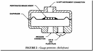
Another source of trouble is blocking of the tube by contaminants in the air. This can be overcome by incorporating a flexible diaphragm in the line to the gauge. The tube can then be filled with a clean fluid which is separated from the air by the diaphragm (Figure 2). The fluid used must be stable at the operating temperature. Commonly used fluids are glycerine and ethylene glycol. The principle can be extended by using the diaphragm unit as a transmitter, separated from the gauge by a length of tubing. The advantage of this is that the gauge can be some distance from the transmitter without affecting the readings.
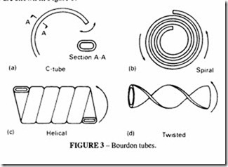
The spiral tube is similar to the C-tube, except that its radius of curvature changes along its length, creating a greater length of tube for a given overall diameter. Because of a greater active length, the arc length of the stroke is greater for a given pressure change. A straight line pick-off from this larger angle of sweep results in non-linearity in output displacement. This may be an advantage in certain circumstances and can be compensated for in the pressure scale.
The helical tube permits a longer tube length for a given radius of curvature. The tube may have two to six turns. The movement of the tip is greater than for the simple C-tube and is more nearly circular. The increase in length of the tube is negligible. The travel of the tip lies in a plane perpendicular to the centre line of the helix, and is proportional to the active length of the tube. The tip travel is much the same as a C-tube of the same length. The twisted tube maintains a straight centre line along the length of the tube but is twisted about the centre line. Internal pressure causes the tube to unwind about the centre line, the angle of rotation being proportional to the applied pressure. The change in length is negligible. Different degrees of twist alter the angular rotation for any given length.
For safety pattern gauges, a solid baffle, forming part of the can structure is interposed between the element and the dial.
Refer to BS 1780 for information about the accuracy, installation, test methods and safety requirements of Bourdon tube gauges.
Electronic pressure gauges
These employ a pressure transducer connected to a resistance bridge, followed by an amplifier. Pressure may be indicated by a meter or a digital readout. The pressure range
of this type can be as high as required. The accuracy depends on the quality of the transducer element and compares favourably with the Bourdon tube.lt is normally within ±1% of the full scale reading, but can be much more accurate.
A portable instrument which can be used for checking the operation and settings of valves and switches is shown in Figure 4. This particular instrument has an accuracy of ±0.2% of full scale reading and a pressure range up to 199.9lb/in2 (14 bar).lt can readily be set to give readings in other units such as heights of water or mercury.
Diaphragm pressure gauges
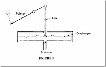
These are suitable only for the measurement of relatively low pressures up to about I bar and vacuum. They are sensitive devices well suited for the measurement or detection of small differential pressures applied to each side of the diaphragm. A typical gauge is shown in Figure 5. The travel of the diaphragm and the stroke available to operate the pointer depends on the cross section and the diameter. Extreme movement may only be obtained at the expense of loss of linearity.
The stroke of a single diaphragm can be extended considerably by employing a slack diaphragm made from a suitable limp material such as nylon or leather. Such a diaphragm requires biasing with spring pressure which opposes the direction of the applied pressure and incorporates stops to limit the movement. The advantage of a slack diaphragm is the large area exposed to pressure, making it sensitive for the measurement of very low pressures.
Metallic diaphragms offer the possibility of working at higher pressure ratings, although the movement is dependent on the amount of corrugation. Sensitivity can be improved by fabricating a series of diaphragms in the form of bellows, although the contour adopted can have a bearing on the linearity of stoke.
Welded metal diaphragms, based on a bellows shape or series of capsules are mostly used for pressure measurements within the range 25 mm wg to 0.35 bar. In capsule types, the capsules form hermetically sealed chambers which may be partially evacuated to render the element more sensitive as in an aneroid barometer.
Bellows type elements formed from thin wall tubing have a higher pressure rating and may be used in several ways. For pressure measurements within the range 0.35 to 2.5 bar or vacuum pressures down to I torr, open ended bellows, enclosed within a chamber are commonly used. Pressure is applied to the chamber, with mechanical movement taken from the free end. The basic design can be modified by the incorporation of spring loading so as to oppose the movement produced by the pressure force. This expands the bellows when the applied pressure is positive and contracts the bellows in the case of a vacuum. See Figure 6.
Sensitivity may be improved by the use of additional bellows to apply spring bias. Also matched bellows may be used each in a separate sealed chamber; the interiors are connected and filled with a liquid with a high bulk modulus, such as oil. Pressure applied to one chamber causes a contrary movement in the other due to the displaced liquid, thus doubling the mechanical movement available from the applied pressure.
Gauge isolator valves
It may sometimes be an advantage to fit a gauge isolator valve, which isolates the gauge from the air pressure, except when it is required to take a reading. Such a valve may be single or multi-station. In the off position the gauge is vented; in one of the operative positions it can select the station to be read. The fitting of such a valve extends the life of the gauge.
Vacuum gauges
Conventional pressure gauges of the capsule or pressure type may be suitable for measurements down to 25 torr. This range is referred to as low vacuum. For high vacuum (lower absolute pressure), special vacuum gauges are used.
The mercury manometer can be used down to 1 torr. The McLeod gauge is a special form of mercury manometer with three limbs, one of which is sealed at the top. Pressure is determined by measurement of the compression of the gas in the sealed limb. This takes the range of the mercury manometer down to I0·6• Itis intended for laboratory use but more robust forms have been developed for general use.
Medium vacuum can be measured by thermocouple and Pirani gauges. These operate by measuring the thermal conductivity of the gas, which is proportional to the number of molecules present (and thus the pressure). The range is from 10·3 to I torr.
For very high vacuums, down to I0·10 torr, special thermionic gauges are available and for extremely high vacuum down to I0·12,mass spectrometer analyser techniques are used.
Pressure measuring devices normally measure the difference between applied pressure and atmospheric pressure and thus indicate gauge pressure (or vacuum pressure in the case of a vacuum gauge). The equivalent absolute pressure is determined by relating the gauge pressure to zero pressure as a datum- see Figure 7. In the case of positive pressure above atmosphere, absolute pressure is the sum of the gauge and the atmospheric pressure (normally assumed to be I bar). Since pneumatics are mainly concerned with gauge pressure less than 10 bar, the difference between absolute and gauge pressure can be significant.


