Application of Pascal’s law
In this section, we shall study two basic applications of Pascal’s law, the hydraulic jack and the air-to-hydraulic booster.
Hydraulic jack
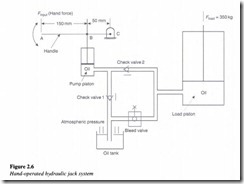
This system uses a piston-type hand pump to power a single acting hydraulic cylinder as illustrated in Figure 2.6.
A hand force is applied at point ‘A’ of handle ‘ABC’, which pivots about point ‘C’. The piston rod of the hand pump is pinned to the input handle at point ‘B’. The hand pump contains a cylinder for aiding the up and down movement. When the handle is pulled, the piston moves up, thereby creating a vacuum in the space below it. As a result of this, the atmospheric pressure forces the oil to leave the oil tank and flow through check valve 1. This is the suction process.
When the handle is pushed down, oil is ejected from the hand pump and flows through the check valve 2. Oil now enters the bottom of the load cylinder. The load cylinder is similar in construction to the pump cylinder. Pressure builds up below the load piston as oil is ejected from the pump. From Pascal’s law, we know that the pressure acting on the load piston is equal to the pressure developed by the pump below its piston. Thus each time the handle is operated up and down, a specific volume of oil is ejected from the pump to lift the load cylinder to a given distance against its load resistance. The bleed valve is a hand-operated valve which when opened, allows the load to be lowered by bleeding oil from the load cylinder back to the oil tank. This cylinder is referred to as single acting because it is hydraulically powered in one direction only.
Air-to-hydraulic pressure booster
Air-to-hydraulic pressure booster is a device used to convert workshop air into a higher hydraulic pressure needed for operating cylinders requiring small to medium volumes of high-pressure oil (Figure 2.7(a)).
It consists of an air cylinder with a large diameter driving a small diameter hydraulic cylinder. Any workshop equipped with an airline can easily obtain hydraulic power from an air-to-hydraulic booster hooked into the airline. Figure 2.7(b) shows an application of the air-to-hydraulic booster. Here the booster is seen supplying high-pressure oil to a hydraulic cylinder used to clamp a work piece to a machine tool table.
Since the workshop air pressure normally operates at around 100 psi, a pneumatically operated clamp would require a relatively larger cylinder to hold the work piece while it is being machined.
Let us assume that the air piston has a 10 sq. in. area and subjected to a pressure of 100 psi. This produces a 1000 lb force on the hydraulic cylinder piston. Thus if the area of the hydraulic piston is 1 sq. in., the hydraulic discharge oil pressure will be 1000 psi. As per Pascal’s law this produces a 1000 psi oil pressure at the small hydraulic clamping cylinder mounted on the machine tool table.
The pressure ratio of the pressure booster can be determined as follows:
Incoming search terms:
- application of pascals law of hydraulic machines
- Pascal\s law booster
- pascals law used in hydraulic pressure booster
- pascals law used in booster
- pascals law of hydraulic pressure
- pascal law based device
- Hydraulic Pressure Tools mail
- Hydraulic Pressure Components mail
- How Pascals law applied in the bicycle pump
- figure of pascals law
- applications of pascals law
- application of pascal\s law to a hand operated hydraulic jack
- which law follow hydrolic system


