After unexpected shut down
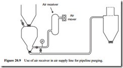
If conveying stops unexpectedly due, for example, to a power supply failure, it may not be possible to start the system again, particularly if the pipeline incorporates a large vertical lift. If the bends at the bottom of any vertical sections are taken out, to remove the material at these points, it may be possible to purge the line clear, if the pipeline is not too long. Should this be a common occurrence on a plant, an air receiver could be fitted between the air mover and the material feeding device. Such an arrangement is illustrated in Figure 20.9. If the material feed into the pipeline is stopped at the instant the power supply fails, the air stored in the receiver could be suf- ficient to purge the line clear of material.
Alternatively a parallel line with connecting valves to the pipeline could be fitted so that the pipeline could be cleared slowly from the end, one section at a time. It should be noted that in the various sketches used to illustrate the points being dis- cussed, different types of system and material feeding arrangements are shown. This is simply to add variety to the notes and avoid repetition. In most cases the modifications to the plant suggested can be applied to any type of pneumatic conveying system and can be utilized with any type of feeder.
In Figure 20.9 a blow tank is specifically shown to illustrate the point that consideration should also be given to the material feeder. With a rotary valve and screw, the material feed will automatically be stopped, but it may not be with a blow tank. It is essential that the material feed should be stopped if the power to the air mover fails. In this event an outlet valve should be provided on the blow tank, with arrangements made for this to close in the event of a power failure.
After a period of time
If a system, that has operated satisfactorily for a long period of time, starts to give trouble with blocked pipelines, wear of the feeding device could be the cause of the problem in the case of positive pressure systems. If the air leakage across the feeding device increases, the air available for conveying the material will decrease. If the loss of air is too great, it is possible that the volumetric flow rate of air that is left will be insufficient to convey the material and the pipeline will block.
A very similar situation exists with regard to vacuum conveying systems. In this case it is the leakage of air into the system, particularly through the discharge valve on the reception hopper. This leakage air is drawn directly into the exhauster and so by-passes the conveying line.
Wear of screw flights, valve seatings of gate lock valves, and rotary valve blades and housings, will all result in a greater leakage of air across the respective feeding device. It is also possible that gradual deterioration in performance of the air mover will have a similar effect, both for positive and negative pressure conveying systems. Most posi- tive displacement air movers operate with very fine clearances and cannot tolerate dust. If they are operated in a dusty environment, and inlet filters are not maintained, wear will occur, particularly if the dust is abrasive. Exhausters on negative pressure conveying systems, and blowers used with closed loop conveying systems, are particu- larly vulnerable in this respect.
Component wear
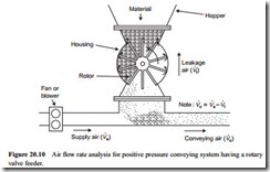
The situation with respect to a rotary valve feeding a positive pressure pneumatic con- veying system pipeline is shown in Figure 20.10 by way of an example. Air will leak across the rotary valve, via the empty pockets and the blade tip clearances, because of the pressure drop across the valve. In low pressure rotary valves, without end plate sealing, air will also leak between the ends of the rotor blades, or the end plate, and the rotor housing. The volumetric flow rate of air delivered from the blower or compres- sor should be specified to take this leakage into account, in order to ensure that there is sufficient air to convey the material through the pipeline.
Most manufacturers of rotary valve feeders provide data on air leakage across their rotary valves so that this can be taken into account in the specification of air require- ments for air movers. The air flow rates to be taken into account are illustrated on Figure 20.10. The leakage rate depends primarily on the size of the rotary valve, the blade tip clearance and the pressure drop across the valve. Rotor speed and the nature of the material being handled can also have an influence.
If there is wear, because of handling an abrasive material, blade tip clearances will increase, and there will be an increase in air leakage. If the air leakage increases, less air will be available to convey the material. If the leakage is such that it results in the conveying air velocity falling below the minimum value, the pipeline will block. These components should be checked for wear. The performance of the air mover should also be checked, as this might be responsible, as mentioned above. In the short term an increase in air loss across a feeding device can be compensated by increasing the air flow rate. In the long term, however, it is recommended that worn components should be replaced.
Pipeline effects
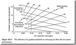
The influence of a gradual increase in air leakage across a feeding device, or a grad- ual reduction in performance of an air mover, is depicted on Figure 20.11. The con- veying characteristics relate to cement conveyed through an 81 mm bore pipeline.
From this it will be seen that the system would operate with a conveying line pressure drop of 0.7 bar, and 0.10 kg/s of air was initially available for conveying the mater- ial. This is well above the minimum necessary for the successful conveying of cement, for the conveying line inlet air velocity would be about 10 m/s and the solids loading ratio, as will be seen from Figure 20.11 would be about 26. Cement is an abrasive
material and with continual wear the air available would gradually reduce until it became insufficient to convey the cement and the pipeline would block.
This can also be a major problem with vacuum conveying systems if filtration units are not maintained and the dust is carried through the exhauster such that its perform- ance deteriorates.
With new material
It is quite possible that a system that operates satisfactorily with one material will be completely unable to convey another material, or even a different grade of the same material. Minimum conveying air velocities can differ markedly from one material to another, as was illustrated in many of the chapters in Part B of this Design Guide. For given conveying conditions, of air flow rate and air supply pressure, different flow rates will be achieved with different materials. Particular care must be exercised in designing any system in which more than one material is to be conveyed, as considered in Chapter 19.
Conveying capability
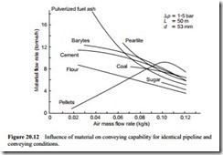
This point is illustrated in Figure 20.12. This is a plot of material flow rate drawn against air flow rate for a range of materials. The curves represent constant pressure drop lines of 1.5 bar taken from the conveying characteristics for each material. They are for a single bore pipeline, 50 m long, 53 mm bore and containing nine 90° bends (pipeline no. 3 in Figure 12.12).
The problem is illustrated very well with Figure 20.12. The materials tested cover a very wide range of material types, sizes and densities, and include representatives of each of the three main modes of conveying. Sugar and coal are typical of materials that can only be conveyed in dilute phase, despite the fact that a high air supply pressure
was used and the pipeline was relatively short. Pulverized fuel ash, barytes, cement and flour were all capable of being conveyed at very low velocity in dense phase in a moving bed type flow. The polyethylene pellets were also capable of being conveyed at very low velocity in dense phase, but in this case it was plug type flow.
It will be seen that the dilute phase materials needed very much higher values of air flow rate than the dense phase materials, and that the coal, with a mean particle size of about 10 mm, could be conveyed at a lower velocity than the granulated sugar. On the right hand side of Figure 20.12, at high air flow rates, all the materials are conveyed in dilute phase suspension flow, and it will be seen that there is a wide spread of material flow rates, for identical conveying conditions, over the range of materials tested. At low air flow rates there is an even wider spread of material flow rates.
It is also possible for different grades of the same material to give totally different conveying line performances, and operating problems resulting from this source can be particularly difficult to recognize. A slight change in particle size distribution or par- ticle shape with some materials can result in a significant change in conveying cap- ability. Particular consideration to this particular problem was given in Section 13.4. As mentioned before, most manufacturers of pneumatic conveying systems have test facilities so that they can convey a material for which a design is required, and so obtain the necessary data. Figure 20.12 will help to reinforce both the need for such design measures, and the need for good troubleshooting procedures.
Air requirements
If a different material is to be conveyed its performance will depend very much upon the air flow rate available, as will be seen from Figure 20.12. If there is insufficient air, it will not be possible to convey the material, unless the pressure is reduced, or more
air is provided. In either case the material flow rate achieved is likely to be much lower and so consideration must be given to the capability of the material feeding device for the new duty. If the air flow rate is increased this might have an adverse effect on the performance of the filtration plant. As will be seen, a change of material can have an influence on many aspects of system design and operation.
