Pressure regulation
Flow velocities in pneumatic systems can be quite high, which can lead to significant flow-dependent pressure drops between the air receiver and the load.
Generally, therefore, air pressure in the receiver is set higher than the required load pressure and pressure regulation is performed local to loads to keep pressure constant regardless of flow. Control of air pressure in the receiver was described in an earlier section. This section describes various ways in which pressure is locally controlled.
There are essentially three methods of local pressure control, illustrated in Figure 3.24. Load A vents continuously to atmosphere.
Air pressure is controlled by a pressure regulator which simply restricts air flow to the load. This type of regulator requires some minimum flow to operate. If used with a dead-end load which draws no air, the air pressure will rise to the main manifold pressure. Such regulators, in which air must pass through the load, are called non-relieving regulators.
Load B is a dead-end load, and uses a pressure regulator which vents air to atmosphere to reduce pressure. This type of regulator is called a three-port (for the three connections) or reliev ing regulator. Finally, load C is a large capacity load whose air volume requirements are beyond the capacity of a simple in-line regulator. Here a pressure control loop has been constructed com-
prising pressure transducer, electronic controller and separate vent valve. This technique can also be used if the pressure regulating valve cannot be mounted locally to the point at which the pressure is to be controlled.
Relief valves
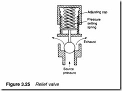
The simplest pressure regulating device is the relief valve shown in Figure 3.25. This is not, in fact, normally used to control pressure but is employed as a backup device should the main pressure control device fail. They are commonly fitted, for example, to air receivers.
A ball valve is held closed by spring tension, adjustable to set the relief pressure. When the force due to air pressure exceeds the spring tension, the valve cracks open releasing air and reducing the pressure. Once cracked, flow rate is a function of excess pressure; an increase in pressure leading to an increase in flow. A relief valve is specified by operating pressure range, span of pressure between cracking and full flow, and full flow rate. Care is needed in specifying a relief valve because in a fault condition the valve may need to pass the entire compressor output.
A relief valve has a flow/pressure relationship and self-seals itself once the pressure falls below the cracking pressure. A pure safety valve operates differently. Once a safety valve cracks, it opens fully to discharge all the pressure in the line or receiver, and it does not automatically reclose, needing manual resetting before the system can be used again.
Non-relieving pressure regulators
Figure 3.26 shows construction of a typical non-relieving pressure regulator. Outlet pressure is sensed by a diaphragm which is pre loaded by a pressure setting spring. If outlet pressure is too low, the spring forces the diaphragm and poppet down, opening the valve to admit more air and raise outlet pressure.
If the outlet pressure is too high, air pressure forces the diaphragm up, reducing air flow and causing a reduction in air pressure as air vents away through the load. In a steady state the valve will balance with the force on the diaphragm from the outlet pressure just balancing the preset force on the spring.
Relieving pressure regulators
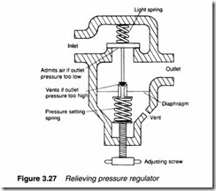
A relieving regulator is shown in Figure 3.27. Outlet pressure is sensed by a diaphragm preloaded with an adjustable pressure
setting spring. The diaphragm rises if the outlet pressure is too high, and falls if the pressure is too low.
If outlet pressure falls, the inlet poppet valve is pushed open admitting more air to raise pressure. If the outlet pressure rises, the diaphragm moves down closing the inlet valve and opening the central vent valve to allow excess air to escape from the load thereby reducing pressure.
In a steady state the valve will balance; dithering between admit ting and venting small amounts of air to keep load pressure at the set value.
Both the regulators in Figure 3.26 and 3.27 are simple pressure regulators and have responses similar to that shown in Figure 3.28, with outlet pressure decreasing slightly with flow. This droop in pressure can be overcome by using a pilot-operated regulator, shown in Figure 3.29.
Outlet pressure is sensed by the pilot diaphragm, which com pares outlet pressure with the value set by the pressure setting spring. If outlet pressure is low the diaphragm descends, while if outlet pressure is high the diaphragm rises.
Inlet air is bled through a restriction and applied to the top of the
main diaphragm. This space can, however, be vented to the exit side of the valve by the small ball valve.
If outlet pressure is low, the pilot diaphragm closes the ball valve causing the main diaphragm to be pushed down and more air to be admitted to the load.
If outlet pressure is high, the pilot diaphragm opens the ball valve and the space above the main diaphragm de-pressurises. This
causes the main diaphragm to rise, opening the central vent allowing air to escape from the load and pressure to be reduced.
Action of pilot diaphragm and inlet air bleed approximates to integral action, giving a form of P + I (proportional plus integral) control. In the steady state, the outlet pressure equals the set pressure and there is no pressure droop with increasing flow.


Hi,
Thanks for the great details about valve, i have bookmarked your blog for the future updates.
We are leading manufacturers company engaged in Solenoid Valve,
Get Valve, Pressure Relief Valve