Stepped pipelines
The design and performance of stepped pipeline systems is another area where little information is available. If a high pressure air supply is used for a pneumatic convey- ing system a high exit velocity will result if a single bore pipeline is used. Apart from adding significantly to problems of erosive wear if the material is abrasive, and to particle degradation if the material is friable, the unnecessarily high velocity towards the end of the pipeline will magnify the flow resistance and thereby restrict the throughput.
If the pipeline is stepped to a larger diameter part way along its length, the velocity in the next section will be reduced. It is clearly necessary to ensure that the new diameter and position of the step are such that the conveying air velocity does not fall below the minimum value for the material otherwise the pipeline is liable to block. Several such steps may be necessary if a very high air supply pressure is to be used. These points,
and others such as pipeline purging, were considered earlier with Figures 9.11–9.16, in relation to both positive pressure and vacuum conveying systems. In this chapter the potential influence of stepping a pipeline on system performance is considered.
Conveying performance data
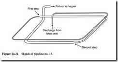
In order to provide some information on the possible benefits of stepped pipeline systems, in terms of increased material flow rate, a major programme of tests was carried out. A 115 m long pipeline of 53 mm bore and incorporating ten 90° bends was built and a sketch of this is given in Figure 14.31 for reference [11].
It was proposed that tests should be carried out in the single bore pipeline, then with the pipeline stepped about half way to 69 mm bore, and finally with the last quarter of the pipeline stepped to 81 mm bore. The stepping of the pipeline was done by simply sleeving one pipeline inside the other and welding to make it pressure tight as shown in Figure 14.32. This was just for convenience as the diameters, with relatively small bore lines, were fairly close. With larger bore pipelines it would be recommended that expansion sections should be fitted to join pipelines, as a degree of energy recovery will be obtained with these at the expansion point (see Figure 10.9).
The material used for testing purposes was a fine grade of fly ash, since it is capa- ble of being conveyed over a very wide range of flow conditions. The conveying characteristics for the fly ash in the above single bore pipeline are presented in Figure 14.33a.
From this it will be seen that the material was conveyed at solids loading ratios of up to 180, with conveying line pressure drop values of up to 3.2 bar, and over a very wide range of air flow rates. These conveying characteristics provide the reference data against which alternative stepped pipeline arrangements can be compared.
For the first comparison with the single bore pipeline, the second half of the pipeline was changed from 53 mm to 69 mm bore pipe. The resulting conveying characteristics are presented in Figure 14.33b and it will be seen that there is a very significant improvement in performance over the entire range of conveying conditions consid- ered. Much higher values of fly ash flow rate were achieved, and with lower values of
conveying line pressure drop, and solids loading ratios of over 200 were achieved in this 115 m long pipeline [11].
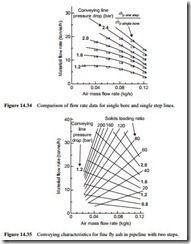
To illustrate the magnitude of the improvement a comparison of the single step and single bore pipelines is given in Figure 14.34. The data points given in Figure 14.34 represent the ratio of fly ash flow rates, and this shows that the material flow rate achieved through the pipeline with a single step was about 1.9 times or 90 per cent greater than that for the single bore pipeline for exactly the same air flow and power requirements. There is little change in the value of this ratio over the entire range of conveying conditions examined. The improvement applies equally to low velocity dense phase conveying, and high velocity dilute phase conveying.
Since the diameter of the first section of the pipeline remains the same, the air mass flow rate remains the same. This has direct application to existing systems, for if a single bore pipeline is used with a high pressure system, the only change may be in terms of
stepping the pipeline. No change need be made to the compressor or to the filtration plant either.
For the second comparison the last quarter of the pipeline was changed from 69 to 81 mm bore. Thus the first 58 m was of 53 mm, the next 29 m was 69 mm and the last 28 m was of 81 mm bore pipe. It should be noted that these are by no means the ideal proportions. They were selected to illustrate the potential improvement that might be achieved over a very wide range of conveying conditions. The optimum position of the pipeline steps will depend very much upon the air supply pressure and pipeline bores available. The resulting conveying characteristics for this pipeline with two steps to larger bore pipe are presented in Figure 14.35. It will be seen from this that a further
improvement over the single step pipeline has been obtained. A similar analysis to that presented in Figure 14.34 showed that the ratio of material flow rates between the double step and single bore pipelines was about 2.2:1.
Velocity profiles
To illustrate the influence that the stepping of the pipeline has had on the conveying air velocity profiles, two representative test runs are presented in Figure 14.36.
In these figures it will be seen that the stepping of the pipeline has had a very significant effect in providing a uniform velocity profile. In the low air flow rate case the maximum velocity of 14.8 m/s was reduced to 8.8 m/s with a single step and to 6.4 m/s with a double step. In the high air flow rate case the maximum velocity of m/s was limited to 24.1 m/s with a single step and to about 20.4 with a double step. In both cases the average velocity values have been significantly lowered with each pipeline.
It is this, to a large extent that has so dramatically increased the conveying performance over the entire range of conveying conditions considered.


