ACTUATORS
One of the outstanding features of fluid power systems is that force, generated by the power supply, controlled and directed by suitable valving, and transported by lines, can be converted with ease to almost any kind of mechanical motion. Either linear or rotary motion can be obtained by using a suitable actuating device.
An actuator is a device that converts fluid power into mechanical force and motion. Cylinders, hydraulic motors, and turbines are the most common types of actuating devices used in fluid power systems. This chapter describes various types of actuating devices and their applications.
HYDRAULIC CYLINDERS
An actuating cylinder is a device that converts fluid power into linear, or straight-line, force and motion. Since linear motion is back-and-forth motion along a straight line, this type of actuator is sometimes referred to as a reciprocating or linear motor. The cylinder consists of a ram, or piston, operating within a cylindrical bore. Actuating cylinders may be installed so that the cylinder is anchored to a stationary structure and the ram or piston is attached to the mechanism to be operated, or the piston can be anchored and the cylinder attached to the movable mechanism.
Actuating cylinders for pneumatic and hydraulic systems are similar in design and operation. Some variations of ram- and piston-type actuating cylinders are described in the following pages.
Ram- Type Cylinders
The terms ram and piston are often used interchangeably. However, a ram-type cylin der is usually considered one in which the cross-sectional area of the piston rod is
more than one-half the cross-sectional area of the movable element. In most actuating cylinders of this type, the rod and the movable element have equal areas. This type of movable element is frequently referred to as a plunger.
The ram-type actuator is used primarily to push rather than to pull. Some applications require simply a fiat surface on the external part of the ram for pushing or lifting the unit to be operated. Other applications require some mechanical means of attachment, such as a clevis or eyebolt. The design of ram-type cylinders varies in many other respects to satisfy the requirements of different applications.
Single-Acting Ram
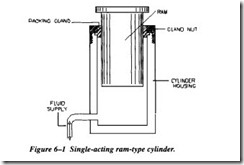
The single-acting ram (Figure 6-l) applies force in only one direction. The fluid that is directed into the cylinder displaces the ram and forces it outward, lifting the object placed on it.
Since there is no provision for retracting the ram by fluid power, when fluid pressure is released, either the weight of the object or some mechanical means, such as a spring, forces the ram back into the cylinder. This forces the fluid back to the reservoir.
Double-Acting Ram
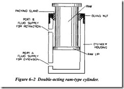
A double-acting ram-type cylinder is illustrated in Figure 6-2. In this cylinder, both strokes of the ram are produced by pressurized fluid. There are two fluid ports, one at each end of the cylinder tube. Fluid, under pressure, is directed to the closed end of the cylinder to extend the ram and apply force. To retract the ram and reduce the force, fluid is directed to the opposite end of the cylinder.
A four-way directional control valve is normally used to control the double-acting ram. When the valve is positioned to extend the ram, pressurized fluid enters port A (Figure 6-2), acts on the bottom surface of the ram, and forces the ram outward. Fluid
above the ram lip is free to flow out of port B, through the control valve, and back to the reservoir.
Normally, the pressure of the fluid is the same for either stroke of the ram. Recall from earlier discussions that force is equal to pressure times area (F = PA). Notice the difference of the areas upon which pressure acts in Figure 6-2. The pressure acts against the large surface area on the bottom of the ram during the extension or pres sure stroke. Since the ram does not require a large force during the retraction stroke, pressure acting on the small area on the top surface of the ram lip provides the neces sary force to retract the ram.
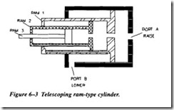
Figure 6-3 shows a telescoping ram-type actuating cylinder. A series of rams is nested in the smallest ram; each ram is hollow and serves as the cylinder housing for the next smaller ram. The ram assembly is contained in the main cylinder assembly, which also provides the fluid ports. Although the assembly requires a small space with all the rams retracted, the telescoping action of the assembly provides a relatively long stroke when the rams are fully extended.
An excellent example of the application of this type of cylinder is the dump truck. The cylinder is used to lift the forward end of the truck bed and dump the load. During the lifting operation, the greatest force is required for the initial lift. As the load is lifted and begins to dump, the required force becomes less and less until the load is com pletely dumped. During the raise cycle, pressurized fluid enters the cylinder through port A (Figure 6-3) and acts on the bottom surface of all three rams. Ram l has the larger surface area and therefore provides the greater force. As ram 1 reaches the end of its stroke the required force is decreased, and ram 2 moves, raising the load. When ram 2 completes its stroke, a still smaller force is required. Ram 3 then moves out ward to finish raising and dumping the load.


