Twin blow tank systems
If two blow tanks are used, rather than one, a significant improvement in performance can be achieved. There are two basic configurations of blow tanks. One is to have the two in parallel and the other is to have them in series. The series arrangement will be considered with feeding systems operating with lock hoppers.
Twin blow tanks in parallel
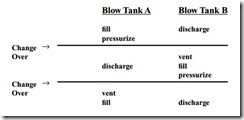
The ratio of the mean flow rate to the steady state material flow rate can be brought close to unity if two blow tanks in parallel are used. While one blow tank is being discharged
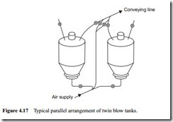
into the conveying pipeline, the other can be de-pressurized, filled, and pressurized, ready for discharging when the other one is empty. By this means almost continuous conveying can be achieved through a common pipeline. This arrangement, however, requires a full set of discharge, vent and isolating valves, and level switches for each blow tank, and an automatic control system to achieve the correct timing. A sketch of a typical parallel arrangement of twin blow tanks is given in Figure 4.17.
From this it can be seen that the blow tank pressurizing process in one blow tank has to be carried out while the material is being discharged from the other. This would require additional air and it would probably not be economically viable for the marginal improvement obtained. To achieve a high tonnage with a single blow tank, a fairly large blow tank would be needed, but with twin blow tanks the tank size can be smaller. The size can be based on a reasonably short blow tank cycle, provided that the two sets of sequences can be fitted into the time allowed.


