The use of stepped pipelines
The use of stepped pipelines is generally associated with the need to reduce the magnitude of the velocity of the conveying air towards the end of the pipeline of a high pres- sure, or high vacuum, pneumatic conveying system. This was considered in detail in Section 9.4. The problems of both erosive wear and material degradation increase expo- nentially with increase in conveying velocity, and so the use of stepped pipelines pro- vides a means by which the excessively high velocities at the end of a conventional single bore pipeline can be reduced.
Stepped pipelines, however, can often be used in cases where different materials need to be conveyed by a common system and so simplify the system design and controls. In other cases it may be possible to use a common system but to feed into pipelines having a different bore. Some examples are given for reference.
Flour and sugar
There is often a requirement for a pneumatic conveying system to convey both flour and sugar. Although sugar comes in a number of grades, it is most commonly produced and available in granulated form. Granulated sugar has little dense phase conveying capabil- ity in a conventional pneumatic conveying system and normally must be conveyed with a minimum conveying air velocity of about 16 m/s. Flour, however, is usually produced as a fine material that can generally be conveyed very easily in dense phase and at low velocity in a conventional pneumatic conveying system.
Conveying data for granulated sugar and wheat flour were presented in Figure 12.11 and were derived from a programme of conveying trials conducted with a high pressure blow tank and conveyed through pipeline no. 3, shown in Figure 12.12. The conveying characteristics are reproduced here in Figure 19.5 for reference. From Figure 19.5a it will be seen that the granulated sugar could only be conveyed in dilute phase and at high velocity, despite the availability of high pressure air, and the maximum value of solids loading ratio achieved was little more than 15. The flour, however, could be conveyed at solids loading ratios up to 200 and with conveying air velocities down to about 3 m/s.
From Figures 19.5a and b it will be seen that the materials are very different in their conveying capability, and with a common pipeline it would not be possible to achieve
optimum conveying conditions for both materials. A compromise would have to be made, but because of the very much higher air requirements of the sugar, it would be the sugar that would dictate the design for the combined system. To illustrate the nature of the problem a design based on the use of an air supply pressure of 2 bar gauge and a con- veying line inlet air velocity 20 per cent greater than the minimum conveying air vel- ocity is assumed. The data for this situation is presented in Table 19.1 [2, 3].
With a minimum conveying air velocity of 16 m/s, a conveying line inlet air velocity of 19.2 m/s is required, and the corresponding material flow rate is about 7 tonne/h. For the same conveying line pressure drop and air flow rate the material flow rate for the flour will be about 6 tonne/h. If the flour was conveyed with a conveying line inlet air velocity of 3.6 m/s, however, the material flow rate achieved would be about 15 tonne/h and hence significantly more economical.
Approximate power requirements and specific energy values for the different cases are also given in Table 19.1. For the case considered it will be seen that the specific energy values for flour and sugar differ by a factor of about 11.5:1, based on optimum conveying conditions, and that the specific energy required for the flour must increase by a factor of about 13.4 in order to use the same air supply and pipeline. The magnitude of the potential differences is such that it is often more economical to install a sep- arate conveying system for each material. By using a stepped pipeline, however, it is possible to achieve optimum conveying conditions for each material with a common conveying system. This is illustrated with two further sets of material below.
Alumina
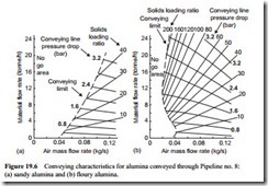
Alumina comes in a range of grades and these are generally referred to as sandy or floury. The sandy grades are coarser than the floury grades, and in general the sandy grades can only be conveyed in dilute phase in a conventional conveying system, but the division between the two is often very close. Conveying characteristics for a typical sandy grade of alumina and for a typical floury grade of floury alumina were presented in Figure 13.21 and are reproduced in Figure 19.6 for reference. Both materials were conveyed through the same pipeline (pipeline no. 8) and a sketch of this is given in Figure 13.20.
Conveying trials were undertaken with air supply pressures up to 3.2 bar for each material. Despite the high pressure, the sandy alumina could only be conveyed in dilute phase, and a minimum conveying air velocity of 10 m/s had to be maintained for suc- cessful conveying. The floury alumina, however, could be conveyed in dense phase, and at only 3 m/s at high values of solids loading ratio. Unlike the flour and sugar, the two grades of alumina showed very similar conveying capabilities for high velocity dilute phase conveying, probably because there was little difference in particle size and shape between the two grades of the material.
Compared with the granulated sugar in Figure 19.5a, the sandy alumina tested was a very fine granular material and so could be conveyed at a much lower velocity than 16 m/s. As a consequence of this, together with a higher air supply pressure, a slightly shorter pipeline and fewer bends, solids loading ratios of just over 40 were achieved, but this is still dilute phase suspension flow. It is suspected that the material is just on the boundary of having dense phase conveying capability, and that a slightly finer grade would probably have the necessary air retention to make dense phase conveying a possibility.
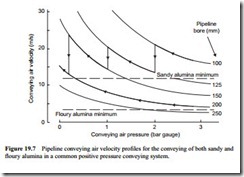
If a 20 per cent margin is allowed on minimum conveying air velocity, in order to specify a conveying line inlet air velocity for design purposes, the minimum value for the sandy alumina will be 12.0 m/s and for the floury alumina it will be 3.6 m/s. To show how a common conveying system might be able to convey both materials, a graph is plotted of conveying air velocity against conveying air pressure and a series of curves for different pipeline bore is superimposed in Figure 19.7.
Figure 19.7 is drawn for a free air flow rate of 0.5 m3/s and onto this are drawn possible velocity profiles for the two materials. Due to the extremely wide difference in con- veying air velocities a single bore line is suggested for the floury alumina, and three
steps are required in the pipeline for the sandy alumina, but it will be seen that the pipeline system meets the requirements of both materials. At entry to the silo a common bore pipe is possible, as illustrated, but this is not necessarily a requirement.
The use of two completely different pipelines is not likely to be a problem. The pipeline used for the floury alumina in Figure 19.7, therefore, could well be stepped part way along its length to 250 mm bore, which could not possibly be used with the sandy alumina. Consideration would have be to given in this case, however, to purging of the pipeline, since the maximum value of conveying air velocity in the pipeline would only be about 10 m/s.
Pulverized fuel ash
Fly ash is another material that can come in a very wide range of sizes, depending upon both the size distribution of the coal generated by the pulverizing mills for combustion in the boiler, and the location of collection hoppers within the boiler plant. The material is essentially the same, wherever it is collected, but the conveying capability of the different grades thus generated can be very considerable [4].
Conveying characteristics for a sample of coarse fly ash from an economizer hopper and those for a sample of fine fly ash from the second field of an electrostatic precipita- tor hopper were shown in Figure 13.25 and are reproduced here in Figure 19.8 [4,5]. Both materials were conveyed through the same pipeline and a sketch of this is given in Figure 13.24. A high pressure top discharge blow tank was also used for the conveying
of these materials, but the pipeline used was of a larger bore and significantly longer that those used for the two previous sets of materials.
The conveying characteristics are shown side by side once again so that a direct visual comparison of the two materials can be made. On these conveying characteristics lines of constant conveying line inlet air velocity have also been added for reference. For the coarse grade of fly ash it will be seen that the minimum conveying air velocity was about 13 m/s and that this did not vary with solids loading ratio. For the fine grade of the fly ash the minimum value of conveying air velocity was about 3 m/s. For the coarse fly ash the maximum value of solids loading ratio was about 15 and for the fine fly ash it was about 160.
Once again these values are dictated by a combination of air supply pressure, min- imum conveying air velocity and conveying distance. It will be seen that the main oper- ating area on the conveying characteristics for the fine fly ash occurs in the no go area for the coarse fly ash, and so the design of a common system for the conveying of both grades of the material may not be immediately obvious, particularly for a vacuum conveying system. Vacuum conveying systems are often used for the transferring of fly ash from the boiler hoppers to intermediate hoppers for onward transfer.
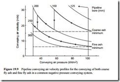
As with the alumina, a graph has been drawn of conveying air velocity against conveying air pressure, with lines of constant pipeline bore superimposed. Onto this has been drawn the conveying air velocity profiles for fine ash and coarse ash. A negative pressure conveying system has been considered, with an air flow rate of 1.0 m3/s at inlet to the compressor at a pressure of 30 kN/m2 absolute.
To avoid confusion an isothermal case has been considered with all temperatures at 300 K, as with the alumina considered above. For the coarse ash a minimum value of conveying air velocity of 16 m/s has been taken, and for the fine ash a value of 6 m/s has been used. The resulting velocity profiles are presented on Figure 19.9.
Once again a common pipeline bore has been used for entry to the reception silo, but as with the positive pressure conveying system considered for the alumina, this is not necessary for negative pressure conveying systems either. Two steps have been recommended for the coarse ash pipeline and this illustrates the general need for stepping pipelines to a larger bore in high vacuum conveying systems. Salient conveying parameters for the two pipelines at the material feed and discharge points are presented in Table 19.2 and a sketch of a typical plant layout is given in Figure 19.10.
A given pneumatic conveying system can be adapted to convey different materials, having widely differing conveying capabilities, quite simply by selecting an appropriate bore of pipeline to meet the minimum conveying air velocity requirements for the mater- ial, and for the given volumetric flow rate of air available. This will involve the use of different pipeline bores at the material feed point, but it will mean that it will be possi- ble to convey the material.
By this means it will also be possible to convey each material at its optimum convey- ing conditions, and so convey materials in both dilute and dense phase with the same conveying system. With high pressure or high vacuum conveying systems it will be pos- sible to step the pipelines to a larger bore along their length, and in these cases it may be possible to merge the pipelines into one and use a common section of pipeline at entry to the reception vessel.
Step location
In all cases where stepped pipelines are employed it is essential that the step is located such that the conveying air velocity does not fall below the minimum conveying air velocity at the step, otherwise the pipeline is likely to block close to that point. If there is any doubt in assessing the correct location of a step it is always wise to position the step a little further down the pipeline where the pressure will be lower, and hence the conveying air velocity higher.


